Intelligent dual-step electronic weighing scale
An electronic scale, intelligent technology, applied in the detailed information of weighing equipment, weighing equipment using elastically deformable parts, weighing and other directions, can solve the problems of use, large errors, and can not be used as a weight scale.
- Summary
- Abstract
- Description
- Claims
- Application Information
AI Technical Summary
Problems solved by technology
Method used
Image

Examples
Embodiment 1
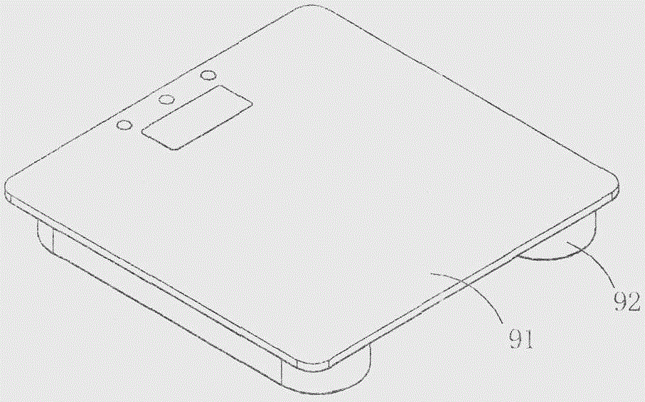
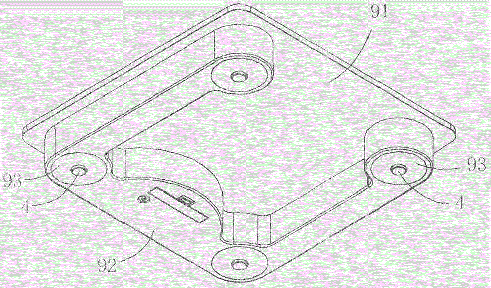
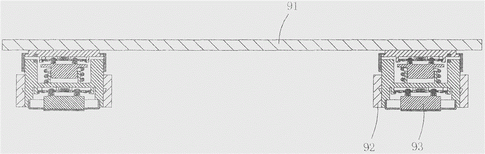
[0030] This embodiment is an intelligent two-stage weighing electronic scale, see Figure 1 to Figure 9 As shown, it includes a carrier plate 91 for placing objects to be weighed; it is characterized in that: it also includes a base 92 arranged under the carrier plate and four double-stage scales for supporting the carrier plate arranged in the base Heavy sensor 93.
[0031] Each double-stage load cell includes a first mount 1, a first precision load cell 2, a first support foot 3, an elastic support 4, a second mount 5, and a second precision load cell 6, which are sequentially crimped. And the second supporting foot 7.
[0032] On the bottom wall of the first mounting seat, there is provided with an annular force-guiding crimping portion 11 and a first card seat 12 located at the center of the force-guiding crimping portion; in this embodiment, the bottom of the force-guiding crimping portion 11 The wall is an annular plane, and the top wall of the first installation seat ...
Embodiment 2
[0059] This embodiment is basically the same as Embodiment 1, the difference is: see Figure 10 to Figure 13 As shown, in this embodiment, the structural shape of the second precision load cell, the second support leg and the cover is different from that of Embodiment 1, and the second precision load cell in this embodiment is still provided with a second fixed part 61, the second force-bearing deformation part 62, and the second resistance strain gauge 63 arranged on the second force-bearing deformation part for detecting the deformation amount of the second force-bearing deformation part; but the second precision in this embodiment The shape of the load cell is similar to the reverse "G" shape, its second fixed part is similar to "C" shape, and the shape of the second force-bearing deformation part is similar to a smaller "C" shape, and it is connected with the second fixed part , combined to form a reverse "G" shape. The measuring range and precision of this second precisi...
Embodiment 3
[0064] This embodiment is basically the same as Embodiment 1, the difference is: see Figure 14 to Figure 17 As shown, in this embodiment, the static contact 91 and the moving contact 92 are no longer provided, and the upper part of the outer peripheral wall of the first support leg is no longer provided with the annular crimping part 32, and the lower part is no longer used as the sliding column part 33.
[0065] In this embodiment, an adjustment hole 35 is provided at the center of the first supporting leg, and a circular connecting column 59 protruding upward from the mounting plate is also provided at the center of the tubular boss 53 of the mounting plate. There is a connecting screw hole 591 at the center of the top wall of the pillar; the tubular boss and the circular connecting pillar form an annular limiting groove 592; the bottom end of the spring is located in the annular limiting groove and abuts against the mounting plate On the part, the top end of the spring abu...
PUM
 Abstract
Description
Claims
Application Information