Center positioning multi-layer permanent magnet governor

A technology of permanent magnet governor and center positioning, which is applied in permanent magnet clutches/brakes, electric brakes/clutches, electrical components, etc., and can solve the problem of uneven magnetic field induced by magnet rings, uneven eddy currents, and energy-saving effects, etc. problems, to achieve the effects of light weight, improved installation accuracy, and saved installation time

Active Publication Date: 2018-05-04
天津市布加迪环保科技发展有限公司
View PDF5 Cites 0 Cited by
  • Summary
  • Abstract
  • Description
  • Claims
  • Application Information

AI Technical Summary

Problems solved by technology

The two shafts are not rigidly connected, and the formation of a cantilever beam structure with two arms lengths of 300-500mm is unavoidable (the weights of the two discs mounted on the shaft end are both 50-80kg); it is very easy to cause radial deformation of the shaft, so Shaft alignment is a difficult point in the installation of this equipment
Although this structure has a certain tolerance for coaxiality (limited to 3mm), even within this limit, this error will cause the magnetic field induced by the magnet ring to be uneven, which will affect the unevenness of the eddy current generated. Seriously affect the energy saving effect of the machine
If the error exceeds the tolerance, it will cause the parts to collide and cause an accident

Method used


Image

  • Center positioning multi-layer permanent magnet governor
  • Center positioning multi-layer permanent magnet governor
  • Center positioning multi-layer permanent magnet governor

Examples


Embodiment Construction

[0016] The technical solutions of the present invention will be further described below through specific examples.

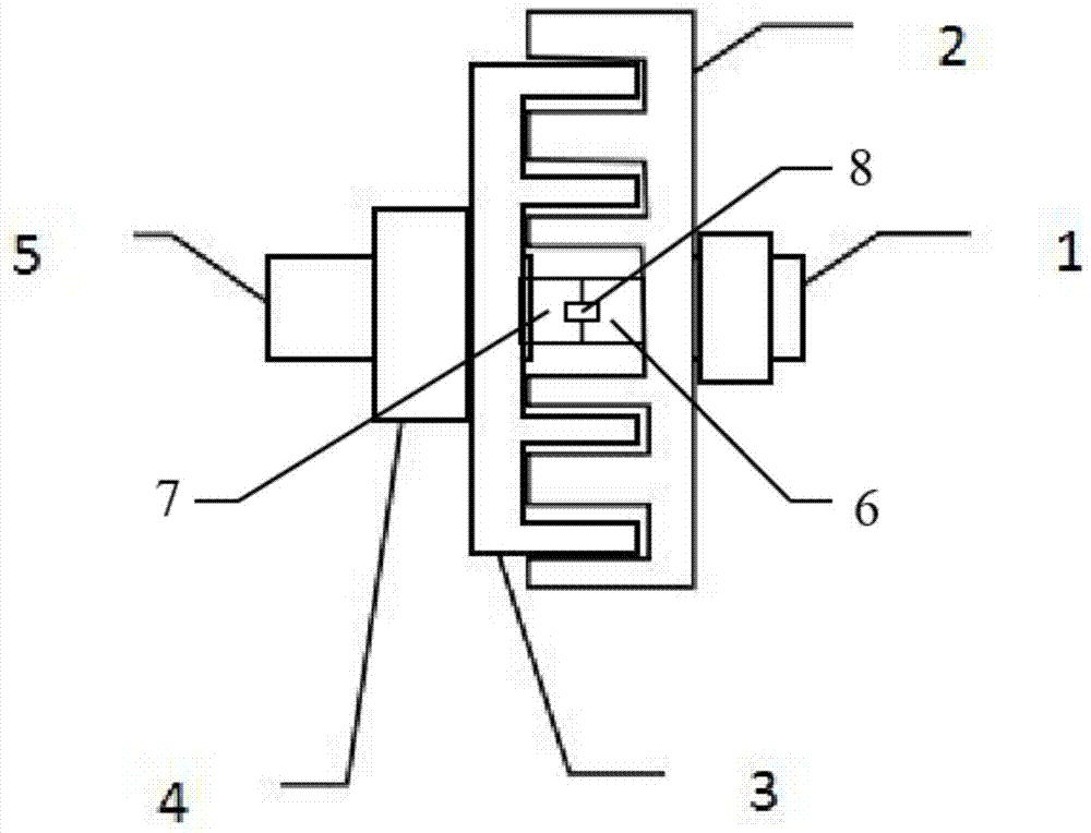
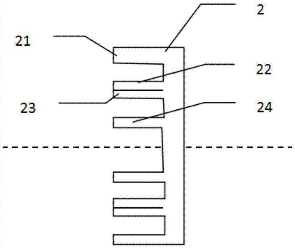
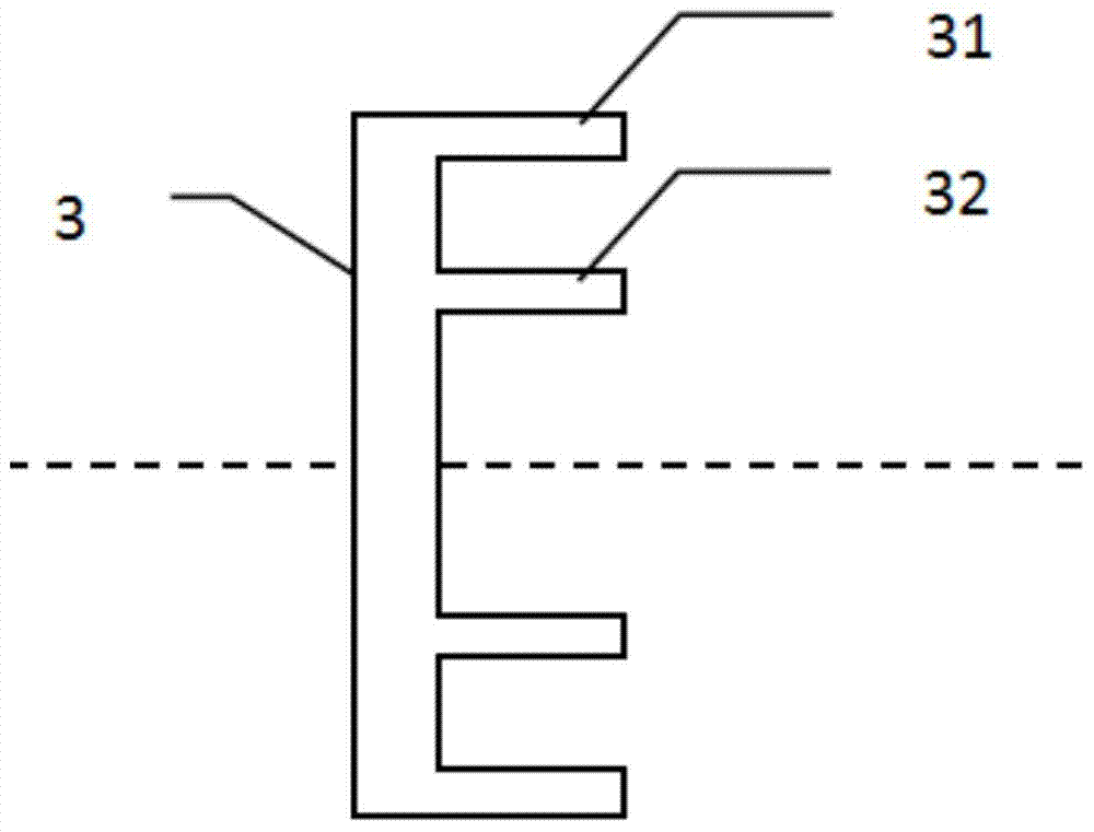
[0017] Such as Figure 1 to Figure 4 As shown, among them, 1 is the motor shaft, 2 is the conductor plate, 21 is the first layer of conductor ring, 22 is the second layer of conductor ring, 23 is the third layer of conductor ring, 24 is the fourth layer of conductor ring, 3 is the magnet Disk, 31 is the magnet ring of the first layer, 32 is the conductor ring of the second layer, 4 is the adjustment mechanism, 5 is the load shaft, 6 is the conductor bearing, 7 is the magnet bearing, 8 is the positioning device, 9 is the conductor disk bearing, 10 It is a magnet disc bearing, 11 is a retaining ring, and 12 is a central positioning shaft.

[0018] Center positioning multi-layer permanent magnet speed governor, including motor shaft, load shaft, conductor disk, magnet disk, adjustment mechanism and positioning device, the motor shaft is connected with the conducto...


PUM


Abstract

The invention provides a centralized positioning multilayer permanent magnet governor. A motor shaft is connected with a conductor plate; a load shaft is connected with a magnet plate through an adjusting mechanism; the adjusting mechanism is used for adjusting the coupling area between a conductor and a magnet; the conductor plate is evenly provided with conductor rings; the conductor rings are symmetrically arranged around the circle center of the conductor plate as the center; a load plate is evenly provided with magnet rings; the magnet rings are symmetrically arranged around the circle center of the magnet plate as the center; the magnet rings and two adjacent conductor rings are arranged in a manner of one-to-one correspondence; the quantity of the magnet rings is one half of that of the conductor rings; the quantity of the conductor rings is multiples of 2; the conductor plate is also provided with a conductor bearing; the magnet plate is also provided with a magnet bearing; the conductor bearing and the magnet bearing are in mutual contact; and a positioning device is arranged between the conductor bearing and the magnet bearing. The centralized positioning multilayer permanent magnet governor has the beneficial effects of being smaller in size, lighter in weight, higher in service power and better in energy-saving effect, and the overall design is more optimal.

Description

technical field [0001] The invention relates to the technical field of drive speed regulating machinery, and more specifically relates to a centrally positioned multilayer permanent magnet speed regulator. Background technique [0002] In recent years, a speed control device has been invented in China, which is mainly composed of a permanent magnet ring and a set of conductor rings, which transmits the rotation from the motor to the load, and realizes the change of the transmitted speed and power with the change of the coupling area, but Due to the need to transfer energy, the diameter of this single-layer structure is very large, especially if the motor power is large, which will lead to excessive self-weight, excessive consumables, and increase heat generation and self-energy consumption. Furthermore, the noise is large and the mechanism stability is poor, so that this device cannot be applied to high-power equipment. [0003] The main part of the permanent magnet speed r...

Claims


Application Information

Patent Timeline
Patent Type & Authority Patents(China)
IPC IPC(8): H02K49/10
CPCH02K49/102
Inventor 张瀛钊李秀玲
Owner 天津市布加迪环保科技发展有限公司
Why Eureka
Try Eureka