
An external counterpart for barrier-free welding of pipelines

An external counterpart and barrier-free technology, applied in welding equipment, auxiliary welding equipment, welding/cutting auxiliary equipment, etc., can solve problems such as poor fusion, insufficient strength, small positioning solder joints, etc., to reduce labor intensity and reduce assembly Effects on incompatibility and avoidance of welding obstacles

Active Publication Date: 2018-02-06
中国石油天然气第一建设有限公司
View PDF7 Cites 0 Cited by
  • Summary
  • Abstract
  • Description
  • Claims
  • Application Information

AI Technical Summary

Problems solved by technology

However, with the advancement of welding methods, when using semi-automatic and automatic welding such as fully automatic hot wire TIG welding, if traditional external counterparts are used for positioning, tack welding is required. When the tack weld is large, root welding is likely to cause incomplete penetration, Poor fusion; the positioning solder joint is too small, and the strength is not enough to easily cause cracking. The high requirements for positioning welding increase the difficulty of welding
In addition, due to the relatively fixed position of the fastening bolts of the traditional external mouthpiece, it cannot be moved to any position, and the adjustment of the wrong side cannot achieve full coverage, and the quality of the mouthpiece is not easy to guarantee

Method used


Image

  • An external counterpart for barrier-free welding of pipelines
  • An external counterpart for barrier-free welding of pipelines
  • An external counterpart for barrier-free welding of pipelines

Examples


Embodiment 1

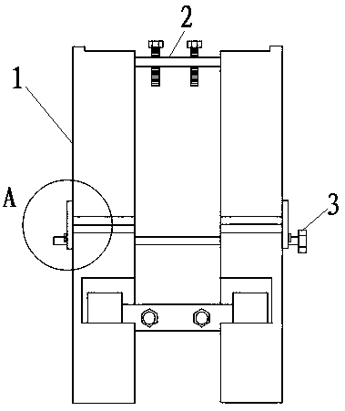
[0037] As shown in the accompanying drawings, this patent is an external counterpart for barrier-free welding of pipelines, which is used for butt welding of pipelines.

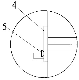
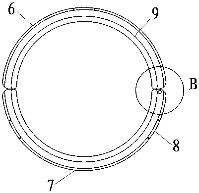
[0038] The snap ring 1 includes an upper half ring 6 and a lower half ring 7; the upper and lower half rings 7 are symmetrically arranged to form a circular ring; the outer sides of the two ends of the upper half ring 6 are respectively provided with a first connection protruding from the upper half ring 6 ports Sheet 4 and the second connecting piece 11, the first connecting piece 4 and the lower half ring 7 are provided with a pin shaft 5, and the second connecting piece 11 and the lower half ring 7 are provided with corresponding through holes 10; the pin shaft The upper and lower half rings 7 on the outer side of the 5 are provided with gaps, and the gaps are used to make the upper and lower half rings 7 of the snap ring 1 open, so that the snap ring 1 can be stuck on the pipe to be welded.

[0039] Both ...

Embodiment 2

[0046] It is the same as Embodiment 1, but the upper and lower surfaces of the slider 12 are inlaid with free-rotating balls, which is to further facilitate the sliding of the slider 12 in the circular chute.

Embodiment 3

[0048] Same as embodiment 1, but the tightening bolt 13 is provided with a handle, which is for the convenience of workers to loosen and tighten the tightening bolt 13 without other tools, so as to save working time.


PUM


Abstract

The invention discloses an external aligning device for barrier-free welding of a pipeline. The external aligning device is used for aligned welding of the pipeline. The external aligning device comprises two clamp rings, three or more connecting sliders and a positioning and connecting bolt; the two clamp rings are symmetrically arranged; the positioning and connecting bolt penetrates through via holes in the two clamp rings, positions and connects the two clamp rings and enables bayonets in the clamp rings to be symmetrical; and sliding blocs at two ends of the three or more connecting sliders are separately arranged in circular sliding chutes through various groups of symmetrical bayonets. Compared with a traditional external aligning device, the external aligning device disclosed by the invention has the advantages that the connecting sliders which can freely move in the corresponding circular sliding chutes are arranged, so that the positions of the connecting sliders can be randomly changed in the corresponding circular sliding chutes, and further the influence on welding operation by constructors is avoided.

Description

technical field [0001] The invention relates to the technical field of pipeline welding, in particular to an external counterpart for barrier-free welding of pipelines. Background technique [0002] According to different construction objects and welding environments, pipe counterparts are divided into two types: internal counterparts and external counterparts. Due to many obstacles, external counterparts not only have many welding joints, but also limit welding and grinding operations, and cannot complete the entire weld. , The difficulty of welding increases and the quality of welding decreases. Therefore, it is only used for assembly and positioning, and it is removed after the positioning welding is completed, and then the formal welding is performed. However, with the advancement of welding methods, when using semi-automatic and automatic welding such as fully automatic hot wire TIG welding, if traditional external counterparts are used for positioning, tack welding is...

Claims


Application Information

Patent Timeline
Patent Type & Authority Patents(China)
IPC IPC(8): B23K37/053
CPCB23K37/0533
Inventor 曹遂军丁自力董留寨聂敏李军赵卫宁田波清刘新海慕香奎王俊峰
Owner 中国石油天然气第一建设有限公司
Learn More