
Fixing device for movable pipeline welding in building construction

A fixing device and building construction technology, applied in the direction of auxiliary devices, welding equipment, auxiliary welding equipment, etc., can solve problems such as insufficient strength, poor fusion, increased positioning welding, etc., and achieve the effect of convenient disassembly and flexible counterparts

Active Publication Date: 2018-07-31
江苏恒健建设集团有限公司
View PDF4 Cites 0 Cited by
  • Summary
  • Abstract
  • Description
  • Claims
  • Application Information

AI Technical Summary

Problems solved by technology

However, with the advancement of welding methods, when using semi-automatic and automatic welding such as fully automatic hot wire TIG welding, if traditional external counterparts are used for positioning, tack welding is required. When the tack weld is large, root welding is likely to cause incomplete penetration, Poor fusion; the positioning solder joint is too small, and the strength is not enough to easily cause cracking. The high requirements for positioning welding increase the difficulty of welding
In addition, due to the relatively fixed position of the fastening bolts of the traditional external mouthpiece, it cannot be moved to any position, and the adjustment of the wrong side cannot achieve full coverage, and the quality of the mouthpiece is not easy to guarantee

Method used


Image

  • Fixing device for movable pipeline welding in building construction
  • Fixing device for movable pipeline welding in building construction
  • Fixing device for movable pipeline welding in building construction

Examples


Embodiment 1

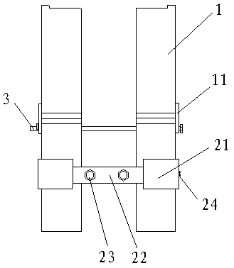
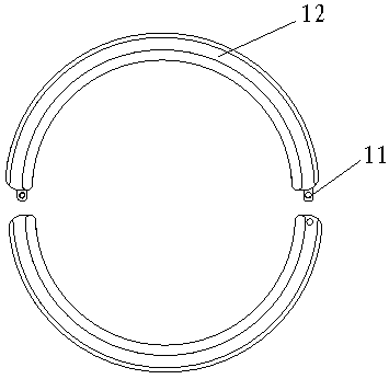
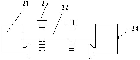
[0028] as attached Figure 1-5 As shown, a fixing device for movable pipeline welding in this patent includes two fixing rings 1, four sliding fasteners 2 and positioning connecting bolts 3;

[0029] The two fixed rings 1 include two symmetrically arranged circular rings and two pin shafts; each fixed ring 1 is composed of two half rings; connecting pieces 11 are arranged on the outer sides of both ends of one of the half rings, and the connecting pieces 11 A pin hole is provided on the top; the two ends of the other half ring are provided with the same pin hole as that on the connecting piece 11; one end of the two half rings is respectively connected by a pin shaft to form a fixed ring 1; the other end is positioned by The connecting bolt 3 connects the two fixed rings 1; there is a gap at the half-ring port at the joint of the pin shaft, so that the two half-rings can be opened and closed around the pin shaft, which is convenient for the fixed ring 1 on the pipeline to be w...

Embodiment 2

[0034] The other structure of this embodiment is the same as that of Embodiment 1, but the movable connection structure of the sliding block of the sliding fastener and the connecting rod is: the end of the connecting rod is provided with a vertical through hole, and the sliding block is provided with a vertical thread The bolt is inserted into the threaded hole through the through hole to connect the slide block with the connecting rod, so that the slide block is arranged at the lower parts of both ends of the connecting piece.

Embodiment 3

[0036] The other structure of this embodiment is the same as that of Embodiment 1, however, the sliding block and one end of the connecting rod are movably connected by a screw: an internally threaded hole is provided at the end of the connecting rod and the sliding block, and an internally threaded hole is provided on the sliding block. Through the threaded hole, the screw fixes the slider to one end of the connecting rod through the internally threaded through hole on the slider and the internally threaded hole at one end of the connecting rod.


PUM


Abstract

The invention discloses a fixing device for movable pipeline welding in construction. The device comprises two fixing rings, three or more sliding fasteners and a positioning and connecting bolt, wherein the two fixing rings comprise two symmetrically arranged fixing rings and two pin shafts, each fixing ring is composed of two semi-rings, and each sliding fastener comprises two sliding blocks, a connecting rod and two puller bolts; a sliding groove is formed in the circular face of the outward side of each fixing ring, the sliding blocks at the two ends of each of the three or more sliding fasteners are located in the sliding grooves of the two fixing rings respectively, and a protrusion part arranged on the inner side of the lower portion of each sliding block can prevent the sliding fasteners from coming off from the sliding grooves. The device has the advantages that butt jointing can be achieved more flexibly, detachment is convenient, labor intensity is relieved, and construction efficiency is improved.

Description

technical field [0001] The invention relates to the technical field of pipeline welding, in particular to a fixing device for movable pipeline welding in building construction. Background technique [0002] In building construction, for example, in the construction of water supply and drainage pipes, it is often necessary to weld different metal pipes together. [0003] According to different construction objects and welding environments, the pipe fitting fixtures are divided into two types: inner fitting and outer fitting. Due to many obstacles, the outer fitting not only has many welding joints, but also restricts welding and grinding operations, and cannot complete the entire weld. The difficulty of welding increases and the quality of welding decreases. Therefore, it is only used for assembly and positioning, and it is removed after the positioning welding is completed, and then the formal welding is performed. However, with the advancement of welding methods, when usi...

Claims


Application Information

Patent Timeline
IPC IPC(8): B23K37/053
CPCB23K37/0533
Inventor 邬宏敏
Owner 江苏恒健建设集团有限公司
Learn More