Fan for motor and manufacturing method of fan

A manufacturing method and fan technology, applied in the direction of manufacturing tools, mechanical equipment, electric components, etc., to achieve firm connection, avoid collision and displacement, and good welding effect

Active Publication Date: 2021-04-20
浙江巴尔电器科技有限公司
View PDF6 Cites 0 Cited by
  • Summary
  • Abstract
  • Description
  • Claims
  • Application Information

AI Technical Summary

Problems solved by technology

[0005] The purpose of the present invention is to provide a motor fan and its manufacturing method. In view of the defects in the prior art, the present invention realizes the fixing of the fan and the rotating shaft through the clamping hoop, which conveniently improves the stability of the connection between the fan and the rotating shaft, and has the advantages of The effect of the connection is firm, avoiding the problem of collision, displacement or connection falling off; on the other hand, the clamping inner diameter of the clamping hoop is adjustable, which can be adapted to shafts of different diameters and shapes, and has a wide range of applications

Method used


Image

  • Fan for motor and manufacturing method of fan
  • Fan for motor and manufacturing method of fan
  • Fan for motor and manufacturing method of fan

Examples


Embodiment Construction

[0042] In conjunction with the above-mentioned accompanying drawings, the motor fan of the present invention and its manufacturing method are described in detail:
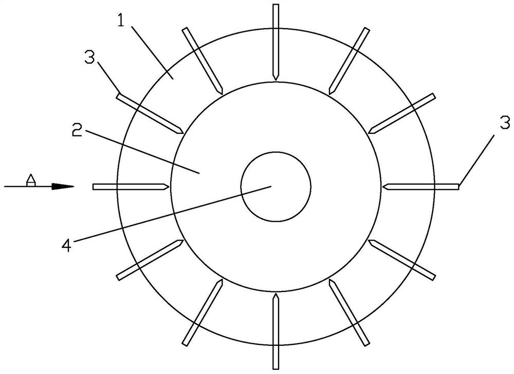
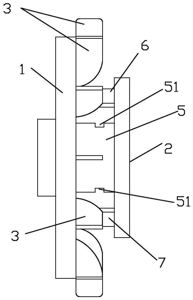
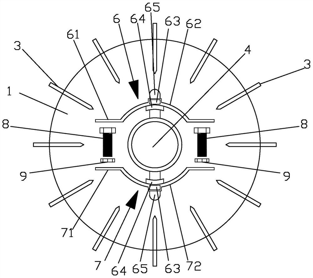
[0043] 1. Motor fan

[0044] Including the base plate 1, the reinforcement plate 2 and the fan blade 3 installed on the base plate 1, the reinforcement plate 2 is connected with the shaft tube 5, the shaft tube 5 is welded with the base plate 1, and the shaft hole 4 is formed, and the motor is connected through the shaft hole 4 shaft; a clamping hoop is provided between the base plate 1 and the reinforcing plate 2, the clamping hoop includes an upper hoop 6 and a lower hoop 7, the upper hoop 6 and the lower hoop 7 are respectively located at the two ends of the shaft cylinder 5, the upper hoop 6 and the lower hoop The hoop 7 is clamped and fixed by the bolt 8 and the nut 9; the upper hoop 6 and the inner side of the lower hoop 7 are equipped with a clamping block 64, and the shaft cylinder 5 is provided with a clam...


PUM


Abstract

The invention discloses a fan for a motor and a manufacturing method of the fan. The fan comprises a base disc, a reinforcing disc and fan blades mounted on the base disc. The reinforcing disc is connected with a shaft barrel, a clamping hoop is arranged between the base disc and the reinforcing disc, the clamping hoop comprises an upper hoop and a lower hoop, and the upper hoop and the lower hoop are clamped and fixed through bolts and nuts; clamping blocks are arranged on the inner side of the upper hoop and the inner side of the lower hoop, clamping holes are formed in the shaft barrel, the clamping blocks are matched with the clamping holes, the clamping blocks of the upper hoop and the lower hoop are inserted into the shaft barrel through the clamping holes to clamp a motor shaft in the shaft barrel, and the distance between the upper hoop and the lower hoop is adjusted through bolts and nuts. The fan and a rotating shaft are fixed through the clamping hoop, on the one hand, the stability of connection between the fan and the rotating shaft is conveniently improved, the effect of firm connection is achieved, and the problem of collision displacement or connection disengagement is solved; and on the other hand, the clamping inner diameter of the clamping hoop is adjustable, the clamping hoop can adapt to rotating shafts with different diameters and different shapes, and the application range is wide.

Description

technical field [0001] The invention belongs to the field of motors, and in particular relates to a motor fan and a manufacturing method thereof. Background technique [0002] A motor is a device that converts electrical energy into mechanical energy. It uses energized coils (that is, stator windings) to generate a rotating magnetic field and acts on the rotor (such as a squirrel-cage closed aluminum frame) to form a magneto-electric power rotation torque. Motors are divided into DC motors and AC motors according to the power used. Most of the motors in the power system are AC motors, which can be synchronous motors or asynchronous motors (the motor stator magnetic field speed and rotor rotation speed do not maintain synchronous speed). The motor is mainly composed of a stator and a rotor. The direction of the current-carrying wire in the magnetic field is related to the direction of the current and the direction of the magnetic field line (magnetic field direction). The w...

Claims


Application Information

Patent Timeline
Patent Type & Authority Applications(China)
IPC IPC(8): F04D29/26F04D29/58F04D29/60H02K9/06B23P15/00B23K37/04B23K37/047B23K31/02B23P19/00B23P19/06
CPCY02P70/50
Inventor 吕锋平
Owner 浙江巴尔电器科技有限公司
Why Eureka
Try Eureka