A thermoelectric battery pack

A technology of thermoelectric batteries and battery packs, which is applied in the direction of thermoelectric device components, etc., can solve the problems of limiting the application range of thermoelectric battery modules, inconvenient installation and use, surface insulation, and limiting the use range of thermoelectric batteries, etc., to achieve low thermal resistance and long working life , The effect of convenient production and assembly

Active Publication Date: 2018-11-02
上海松芝酷能汽车技术有限公司
View PDF1 Cites 0 Cited by
  • Summary
  • Abstract
  • Description
  • Claims
  • Application Information

AI Technical Summary

Problems solved by technology

Due to the brittleness of ceramics, it is not resistant to vibration and impact, which also limits the range of use of thermoelectric batteries
[0004] Chinese patent CN201523027U discloses "a thermoelectric battery module with resin electrical insulation". Although it solves the problem of vibration resistance and impact resistance of the ceramic thermoelectric battery module, it is still provided as a single module, which is inconvenient to install and use. The problem of surface insulation has not been solved, and these deficiencies also limit the application range of the resin-insulated thermoelectric battery module

Method used


Image

  • A thermoelectric battery pack
  • A thermoelectric battery pack
  • A thermoelectric battery pack

Examples


Embodiment 1

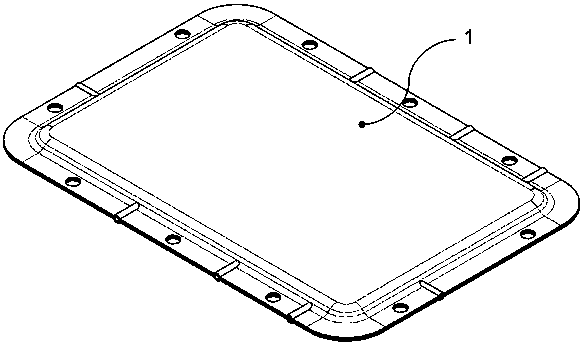
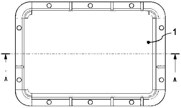
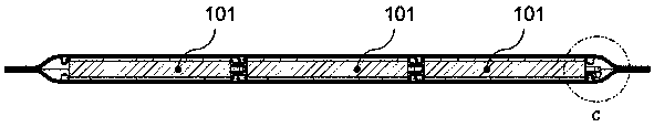
[0046] see Figure 1-4. A thermoelectric battery pack 1, comprising a thermoelectric battery unit 101, an upper case 2, an upper case heat transfer layer 3, a lower case 4, a lower case heat transfer layer 5, an upper and lower case heat insulation pad 6, an upper buffer heat conduction layer Shock-absorbing pad 7, lower buffer heat-conducting shock-absorbing pad 8. The thermoelectric battery unit 101 is the smallest structural unit of the thermoelectric battery pack, and its working surface is made of ceramic materials; the shape of the thermoelectric battery unit 101 is round or square, and its height is between 3 and 6 mm. The width is between 10 and 80mm. The upper case 2 and the lower case 4 adopt stamping structural parts or die-casting structural parts, and a number of positioning slots corresponding in size and capable of installing the thermoelectric battery unit 101 are provided inside the upper case 2 and the lower case 4 Shaped structures 401, 402 can limit the ...

Embodiment 2

[0055] see Figure 7-8 . A thermoelectric battery pack, the components of which are basically the same as those in Example 1. The difference is that the arrangement methods of the upper shell heat transfer layer 3 and the lower shell heat transfer layer 5 are different.

[0056] The specific method of embodiment 2 is: first attach the upper casing heat transfer layer 3 with an area smaller than the outer surface of the upper casing 2 to the outer surface (working area) of the upper casing 2, and place the non-working layer on the outer surface of the upper casing 2 There is no upper shell heat transfer layer 3 in the area; then the lower shell heat transfer layer 5 with an area smaller than the outer surface of the lower shell 4 is pasted on the outer surface of the lower shell 4 (working area), and on the outer surface of the lower shell 4 The non-working area has no lower shell heat transfer layer 5; the edge of the upper shell 2 without the upper shell heat transfer layer...

Embodiment 3

[0059] see Figure 9-15 . A thermoelectric battery pack, the components of which are basically the same as those in Embodiment 1. The difference is:

[0060] The hole structure for installation and positioning provided around the upper casing 2 and the lower casing 4 and the through-hole structure that facilitates the wiring of the positive pole 9, the negative pole 10 and the temperature sensor 11 of the thermoelectric battery unit 101 are more obvious (see Figure 10 , 11 ).

[0061] The arrangement methods of the upper case heat transfer layer 3 and the lower case heat transfer layer 5 are different. The specific method of embodiment 3 is: first attach the upper shell heat transfer layer 3 with an area smaller than the outer surface of the upper shell 2 to the outer surface (working area) of the upper shell 2, and place the non-working layer on the outer surface of the upper shell 2 There is no upper shell heat transfer layer 3 in the area; then the lower shell heat tr...


PUM


Abstract

The invention relates to a thermoelectric battery pack, comprising upper and lower casings, heat transfer layers of the upper and lower casings, and thermoelectric battery units; A number of groove-shaped positioning structures for the thermoelectric battery unit, whereby the upper case and the lower case can be embedded with thermoelectric battery units arranged in a 3×3 arrangement, or connected in parallel or in series, or mixed in parallel and in series; each thermoelectric battery unit is equipped with Positive and negative poles and temperature sensors; there are upper and lower cushioning heat conduction and shock absorbing pads in the gap between the thermoelectric battery unit and the upper and lower shells; the upper and lower shells are connected by screw joints or spot welding to form a battery pack as a whole. The invention is reasonably strong, sealed and shock-resistant through structural design; through grinding and polishing the working surface and adjusting the parallelism, the parallelism and precision of the working surfaces of the upper and lower shells are guaranteed and has low thermal resistance; the production and assembly are convenient and easy to use , long working life, can be actively promoted and applied.

Description

technical field [0001] The present invention relates to the technical field of thermoelectricity, relates to battery pack technology, specifically, a thermoelectric battery pack. Background technique [0002] The thermoelectric battery is an applied product that works according to the "Peltier effect" and "Seebeck effect". It is a solid-state device without rotating parts. Products that emit hazardous substances such as HCFCs; the same thermoelectric cell can be used for cooling as well as heating by simply changing the direction of the current flow; it can be used to generate electricity given different temperatures on the upper and lower surfaces. In addition, it can be installed and operated at any angle and can precisely control the temperature by adjusting the voltage or current. Due to these series of advantages, the thermoelectric battery has been widely used in various fields such as industry, agriculture, scientific research and national defense. Moreover, with th...

Claims


Application Information

Patent Timeline
Patent Type & Authority Patents(China)
IPC IPC(8): H01L35/02
CPCH10N10/80
Inventor 尹湘林覃峰
Owner 上海松芝酷能汽车技术有限公司
Why Eureka
Try Eureka