A rotor axial clearance measuring device for automobile cooling fan motor

A technology of motor rotor shaft and cooling fan, which is applied in mechanical clearance measurement, electromechanical devices, manufacturing of motor generators, etc. problems, to achieve the effect of convenient descent to the lowest position, high measurement efficiency, and reduction of manual participation

A technology of motor rotor shaft and cooling fan, which is applied in mechanical clearance measurement, electromechanical devices, manufacturing of motor generators, etc. problems, to achieve the effect of convenient descent to the lowest position, high measurement efficiency, and reduction of manual participation

CN105958745BActive Publication Date: 2018-05-01JIANGSU LANGXIN ELECTRIC

Image

  • A rotor axial clearance measuring device for automobile cooling fan motor
  • A rotor axial clearance measuring device for automobile cooling fan motor
  • A rotor axial clearance measuring device for automobile cooling fan motor

Examples


Embodiment Construction

[0021] The present invention will be further described in detail below through specific embodiments.

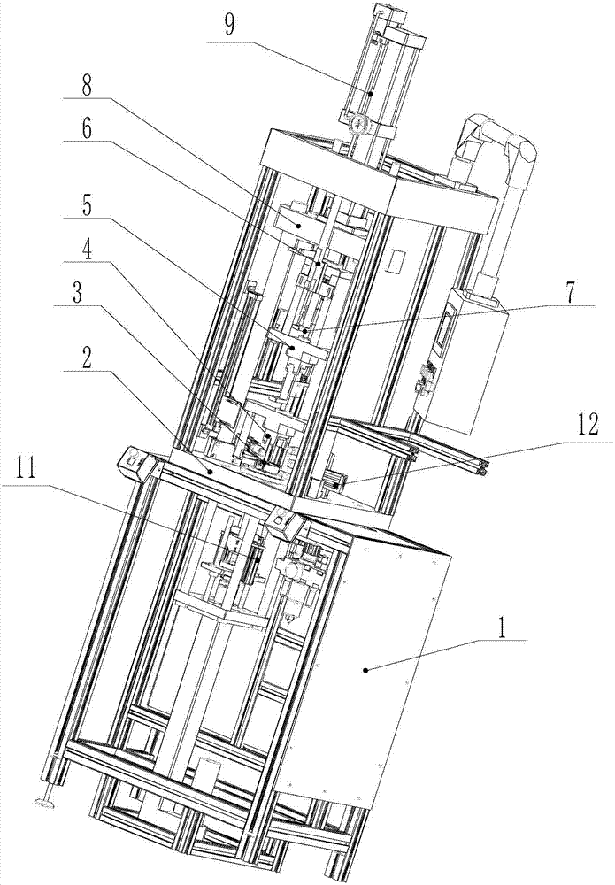
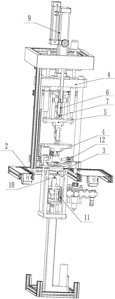
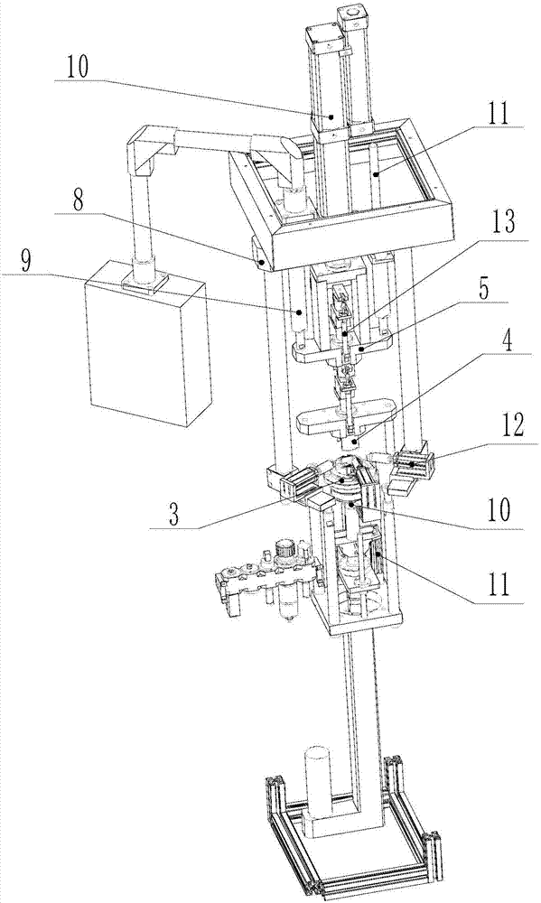
[0022] Such as Figure 1 to Figure 3 As shown, a device for measuring the axial gap of the rotor of an automobile cooling fan motor includes a frame 1, on which an operating platform 2 is provided, and a lower part matching the front end cover of the motor is fixed on the operating platform 2 The concave mold 3 is provided with a jack for inserting the front end of the motor rotor shaft on the lower concave mold 3, and the frame 1 is vertically slidably installed under the operating platform 2 with a lower top that matches the lower end of the motor rotor shaft. Rod 10, the lower ejector bar 10 is driven by the lower ejector lifting power device 11, the frame 1 is vertically slidably mounted above the operating platform 2 with an upper die 4 that matches the rear end cover of the motor, so The upper die 4 is driven by the upper die lifting power device 9. The upper die 4 is pro...


PUM


Abstract

The present invention discloses an axial clearance measuring apparatus of a rotor of an automobile cooling fan motor. The apparatus includes a rack. The rack is provided with an operation platform. A lower female die is fixed on the operation platform. The lower female die is provided with a jack. A lower ejector pin is vertically installed on the rack in a sliding manner. The lower ejector pin is driven by a lower ejector pin lifting power apparatus. An upper pressing die is vertically installed on the rack in the sliding manner. The upper pressing die is provided with a through hole corresponding to a motor rotor shaft. An upper ejector pin corresponding to the rear end of the motor rotor shaft is vertically installed on the rack in the sliding manner. The upper ejector pin is in the through hole and is driven by an upper ejector pin lifting power apparatus. The rack is provided with a measuring mechanism for measuring an upper ejector pin moving distance or a lower ejector pin moving distance. The axial clearance measuring apparatus can measure an axial clearance of the rotor of the motor rapidly, a measurement result is more accurate, measurement efficiency is higher, and the apparatus can be applied to axial detection of clearances of a large scale of motor rotors.

Description

Technical field [0001] The invention relates to an axial gap measuring device, in particular to a rotor axial gap measuring device of an automobile cooling fan motor. Background technique [0002] The cooling fan of the vehicle is driven by a motor. This motor has a rotor. The rotor shaft of the rotor is supported by bearings at the front and rear ends and installed on the end covers at both ends. The end of the motor’s rotor shaft protruding from the stator shell is the front end. One end of the rotor shaft is the rear end, so the rear end of the rotor shaft is rotatably mounted on the back end cover, and the front end of the rotor shaft penetrates the front end cover and is rotatably mounted on the front end cover through the bearing, and the front end cover is clamped and fixed to the stator shell. The rotor has an armature composed of a coil with an iron core, and a segmented commutator for supplying current, and a sliding contact for power supply is provided on the commutato...

Claims


Application Information

Patent Timeline
01 May 2018
Publication
CN105958745B
IPC
H02K15/00; G01B5/14
CPC
G01B5/14; H02K15/00
Inventors
姚小君; 卢勇