DC-DC converting circuit

A DC-DC and conversion circuit technology, applied in the direction of converting DC power input to DC power output, electrical components, and adjusting electrical variables, can solve problems such as high cost of implementation, large common-mode interference, and high voltage requirements, and achieve reduced implementation Difficulty, reducing current ripple, reducing the effect of filters

Active Publication Date: 2016-09-21
SHENZHEN YINGFEIYUAN TECH CO LTD
View PDF3 Cites 16 Cited by
  • Summary
  • Abstract
  • Description
  • Claims
  • Application Information

AI Technical Summary

Problems solved by technology

[0004] The invention provides a DC-DC conversion circuit, which solves the technical problems in the prior art that the DC-DC conversion circuit has high voltage requirements for electronic devices, high implementation cost, and large common-mode interference

Method used


Image

  • DC-DC converting circuit
  • DC-DC converting circuit
  • DC-DC converting circuit

Examples


Embodiment 1

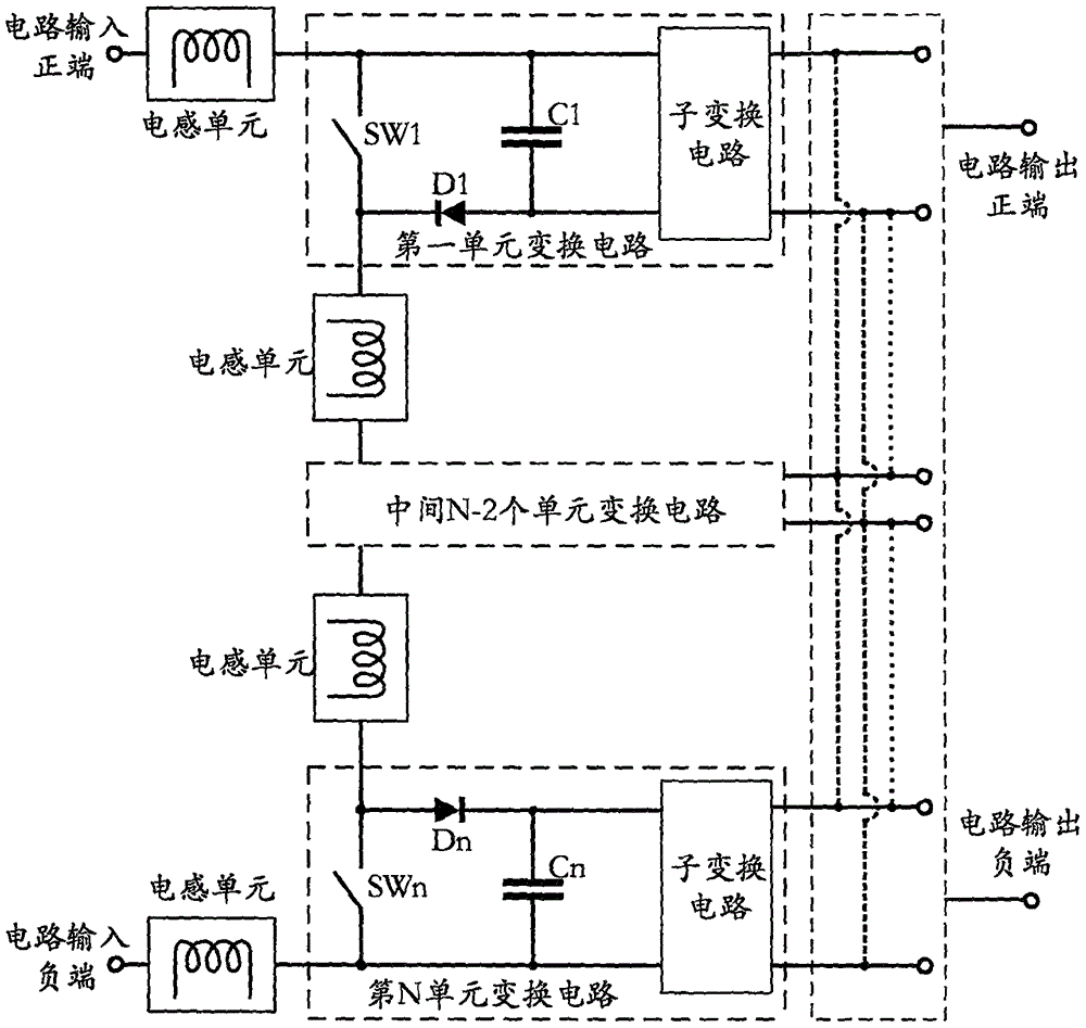
[0019] Such as figure 1 As shown, it is a DC-DC conversion circuit, including: N unit conversion circuits, M inductance units, circuit input positive terminals, circuit input negative terminals, circuit output positive terminals and circuit output negative terminals, the first unit The positive input terminal of the conversion circuit is connected to the positive input terminal of the circuit through an inductance unit or directly, and the negative input terminal of the conversion circuit of the Kth unit is connected to the positive input terminal of the K+1th unit conversion circuit through an inductance unit or directly. connection, K, M and N are natural numbers, K

Embodiment 2

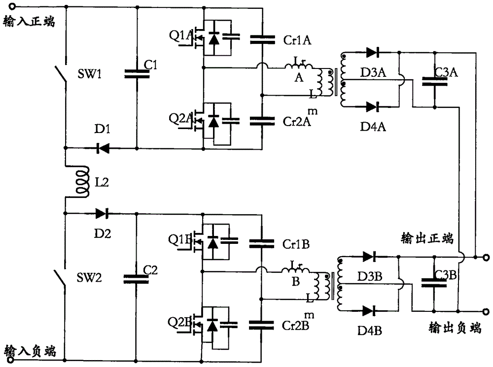
[0038] Such as figure 2 As shown, it is a schematic diagram of the second embodiment of the present invention, the number of unit conversion circuits N is 2, an inductance unit is selected for the inductance unit and connected in series between the first unit circuit and the second unit circuit, and the positive input terminal is directly connected to the first unit circuit. One end of the unit circuit is connected, and the input negative terminal is directly connected to one end of the second unit circuit, so that there is no high-frequency voltage jitter between C1 and C2 and the input, and the best effect of eliminating common mode interference is achieved; in the first and second unit circuits The commonly used half-bridge LLC circuit is selected for the sub-conversion circuit, and its output terminal is connected in parallel; by the half-bridge LLC voltage gain formula

[0039] M = V o ...

Embodiment 3

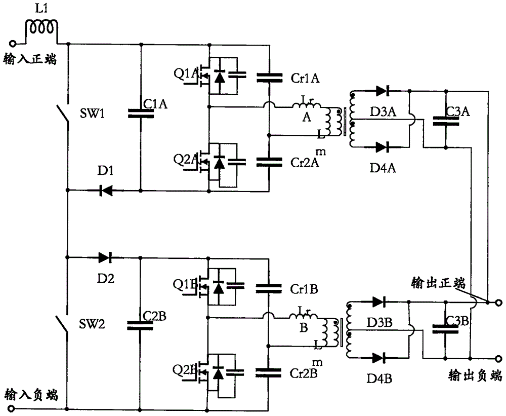
[0045] Such as image 3 As shown, it is a schematic diagram of the third embodiment of the present invention, the circuit takes the number of circuit groups N as 2, and the inductance unit selects an inductance unit and connects it in series between the input positive terminal and the first unit circuit, the first and the second unit The circuits are directly connected in series, and the input negative terminal is directly connected with one terminal of the second unit circuit. The sub-converting circuits in the first and second unit circuits also select the commonly used half-bridge LLC circuit, and the output ends are connected in parallel. In this way, the voltage of C2 has no high-frequency jitter relative to the input, but the voltage of C1 has high-frequency jitter relative to the input. Therefore, for the problem of common-mode interference, this embodiment only reduces the common-mode interference, which is a suboptimal solution compared to the first embodiment. Same ...


PUM


Abstract

The invention relates to the electric power electronic technical field, and discloses a DC-DC converting circuit which comprises N unit converting circuits, M inductance units, a circuit input positive terminal, a circuit input negative terminal, a circuit output positive terminal and a circuit output negative terminal. The input positive terminal of the first unit converting circuit is in connection with the circuit input positive terminal through an inductance unit, and is directly in connection with the circuit input positive terminal; the input negative terminal of a Kth unit converting circuit is in connection with the input positive terminal of a (K+1)th unit converting circuit through the inductance unit or is directly in connection with the input positive terminal of a (K+1)th unit converting circuit; K, M and N are all natural numbers, KN, and 1=M=(N+1). The input negative terminal of an Nth unit converting circuit is in connection with the circuit input negative terminal through the inductance unit or is directly in connection with the circuit input negative terminal; the outputs of the N unit converting circuits are in parallel connection or in series connection, and are in connection with the circuit output positive terminal and the circuit output negative terminal. The DC-DC converting circuit reduces the cost, eliminates or reduces common mode interference, realizes interleaving control, decrease input and output current ripples, and is in favor of reducing filters and implementation difficulty.

Description

technical field [0001] The invention relates to the technical field of power electronics, in particular to a DC-DC conversion circuit. Background technique [0002] In industrial applications, there is a large demand for conversion of wide input and upper limit to high voltage (about 200V ~ 800V), such as converting the high voltage of the power battery pack to 24V / 12V output in electric vehicles. If a single-stage circuit (such as active clamp forward) is used for direct DC-DC conversion, although the technology is mature, the topology and control are simple, and the number of devices used is small; but special high-voltage switching devices (such as 900-1200V MOS tube), the price is expensive; at the same time, the efficiency of the converter is not high under wide input voltage. Therefore, in applications with higher requirements, it is a better method to implement it by means of two-stage transformation. The more common two-stage conversion method is that the front sta...

Claims


Application Information

Patent Timeline
Patent Type & Authority Applications(China)
IPC IPC(8): H02M3/335H02M3/338H02M1/44H02M1/14
CPCH02M1/143H02M1/44H02M3/33569H02M3/3381
Inventor 王彩凤
Owner SHENZHEN YINGFEIYUAN TECH CO LTD
Why Eureka
Try Eureka