
Sports leg pressing trainer

A technology for trainers and leg presses, applied in gymnastics equipment, sports accessories, etc., can solve the problems of users slipping, limb strain, and easy sliding of feet forward, so as to avoid slipping and ensure safe use

Inactive Publication Date: 2016-09-28
孙至真
View PDF8 Cites 9 Cited by
  • Summary
  • Abstract
  • Description
  • Claims
  • Application Information

AI Technical Summary

Problems solved by technology

[0002] Leg pressing can exercise the stretching ability of leg ligaments, which is the basic skill of various sports. It is generally necessary to stretch the limbs before training to prevent limb strains during training, especially for martial arts and gymnastics. The leg training of sports events more needs to realize the rehearsal of some basic movements by pressing the legs, so the leg pressing of sports training or the limb stretching before exercise all will use the leg pressing apparatus, but the existing leg pressing trainer still has There are problems, such as the patent application number 201620046548.4, which includes the base and the first pillar and the second pillar located at both ends of the top of the base. The driving wheel is installed on the first screw, the second screw is installed on the end of the cavity away from the motor, the driven wheel is installed on the second screw, the transmission belt is set between the driven wheel and the driving wheel, and the first screw nut is installed on the first screw. The first connecting column is set on the first screw nut, the first chute is set inside the first pillar, the second screw nut is set on the second screw nut, and the second connecting column is set on the second screw nut. Although it can be used flexibly and conveniently, the user When the leg is pressed, the foot is easy to slide forward, causing the user to slip and fall, causing injury to the user

Method used


Image

  • Sports leg pressing trainer
  • Sports leg pressing trainer

Examples


Embodiment Construction

[0013] The following will clearly and completely describe the technical solutions in the embodiments of the present invention with reference to the accompanying drawings in the embodiments of the present invention. Obviously, the described embodiments are only some, not all, embodiments of the present invention. Based on the embodiments of the present invention, all other embodiments obtained by persons of ordinary skill in the art without making creative efforts belong to the protection scope of the present invention.

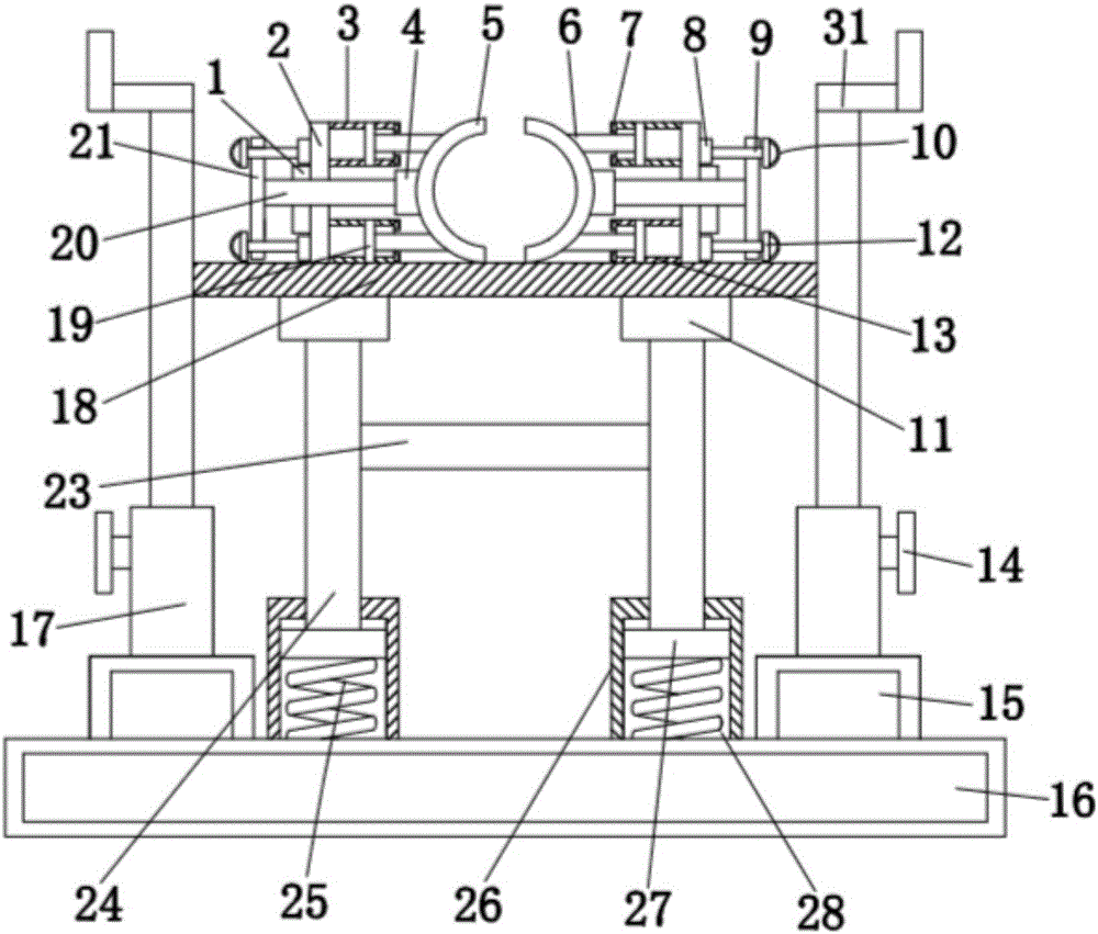
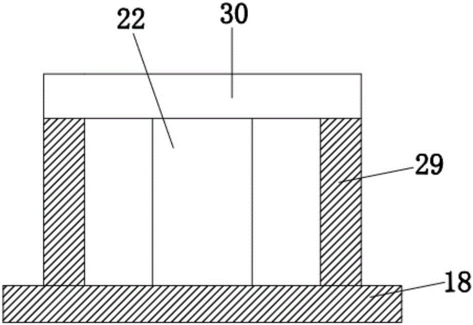
[0014] see Figure 1-2 , the present invention provides a technical solution: a sports leg press trainer, including a base 16, the left and right sides of the top of the base 16 are provided with a stable seat 15, the inner side of the stable seat 15 is provided with a limit tube 26, the The inside of the limiting cylinder 26 is provided with a placement groove 28, and the interior of the placement groove 28 is provided with a shock absorbing spring 25, throug...


PUM


Abstract

The invention discloses a sports leg pressing trainer which comprises a base. Stabilizing bases are arranged on the left side and the right side of the top end of the base respectively. A pressing rod is arranged on the inner side of a height adjusting rod. Fixing plates are arranged on the left side and the right side of the top end of the pressing rod respectively. Slide grooves are formed in the upper end and the lower end in a slide cylinder respectively. A sliding plate is connected with the slide grooves in a sliding mode. A fixing ring is arranged on the inner side of a slide rod. A connecting piece is arranged at the center of the outer side of the fixing ring. According to the sports leg pressing trainer, by means of footrests, feet of a user are placed and supported, and ankles of the user are fixed; by rotating a handle inwards, the handle drives a limiting plate and a fixing rod to move inwards, and the fixing rod and a fixing base are matched to fix a moving rod, so the fixing ring is fixed, it is effectively avoided that feet slide forwards in the leg pressing process of the user and the user slips and falls, and the use safety of the user is ensured.

Description

technical field [0001] The invention relates to the technical field of sports equipment, in particular to a sports leg press trainer. Background technique [0002] Leg pressing can exercise the stretching ability of leg ligaments, which is the basic skill of various sports. It is generally necessary to stretch the limbs before training to prevent limb strains during training, especially for martial arts and gymnastics. The leg training of sports events more needs to realize the rehearsal of some basic movements by pressing the legs, so the leg pressing of sports training or the limb stretching before exercise all will use the leg pressing apparatus, but the existing leg pressing trainer still has There are problems, such as the patent application number 201620046548.4, which includes the base and the first pillar and the second pillar located at both ends of the top of the base. The driving wheel is installed on the first screw, the second screw is installed on the end of t...

Claims


Application Information

Patent Timeline
Patent Type & Authority Applications(China)
IPC IPC(8): A63B23/04
CPCA63B23/0488A63B2023/006
Inventor 孙至真
Owner 孙至真
Learn More