Supercharge Your Innovation With Domain-Expert AI Agents!

Vibration disc position adjusting device applicable to thread rolling machine

An adjustment device and vibration plate technology, applied in the mechanical field, can solve the problems of inability to adjust the position of the vibration plate, inconvenient installation of the vibration plate and the feeding mechanism, and low degree of automation, and achieve the effects of simple structure, convenient installation, and convenient operation

Inactive Publication Date: 2016-09-28
ZHEJIANG KEJIA MACHINERY
View PDF8 Cites 2 Cited by
  • Summary
  • Abstract
  • Description
  • Claims
  • Application Information

AI Technical Summary

Problems solved by technology

[0004] Although the above solution solves the problem of low automation of the existing thread rolling machine to a certain extent, the solution still exists: the position of the vibrating plate cannot be adjusted, and when it is necessary to replace the vibrating plate of different sizes, the vibration plate and the feeding Problems such as inconvenient installation between institutions

Method used


Image

  • Vibration disc position adjusting device applicable to thread rolling machine
  • Vibration disc position adjusting device applicable to thread rolling machine
  • Vibration disc position adjusting device applicable to thread rolling machine

Examples


Embodiment Construction

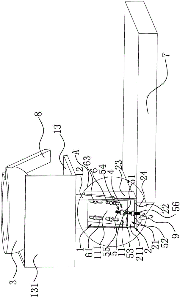
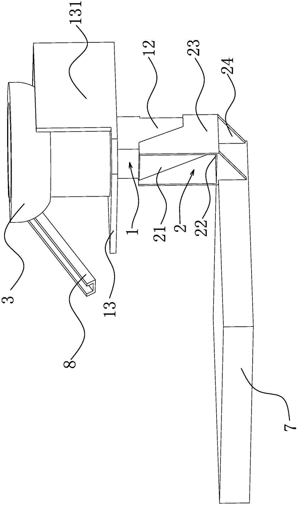
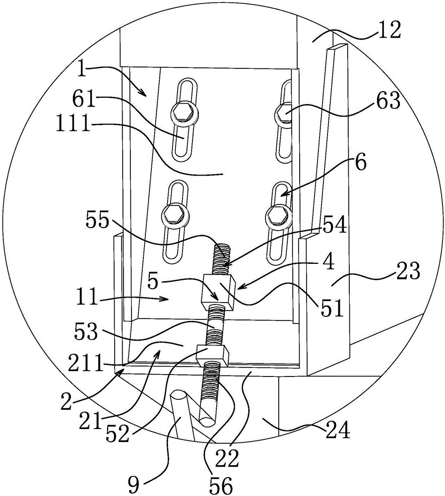
[0021] Such as figure 1 As shown in Figure 3, this device is applicable to the vibration plate position adjustment device of the thread rolling machine. This position adjustment mechanism includes an upper frame body 1 connected with the vibration plate body 3. The lower end of the upper frame body 1 is provided with an upper inclined surface 111 extending downward. The upper inclined plate 11, the lower end of the upper frame body 1 is movably connected with the lower frame body 2, the upper end of the lower frame body 2 is provided with a lower inclined plate 21 extending upwardly and corresponding to the lower inclined surface 211 corresponding to the upper inclined surface 111, and the upper inclined plate 11 It is slidingly connected with the lower sloping plate 21, and there is a device between the upper sloping plate 11 and the lower sloping plate 21 to enable the lower sloping plate 21 to have an upward thrust on the upper sloping plate 11, and the upper sloping plate 1...


PUM


Abstract

The invention provides a vibration disc position adjusting device applicable to a thread rolling machine, and solves the technical problem that in the prior art, the position of a vibration disc cannot be adjusted. The vibration disc position adjusting device applicable to the thread rolling machine comprises an upper frame body connected with a vibration disc body, wherein an upper inclined plate with an upper inclined surface which is inclined and extends downwards is arranged at the lower end of the upper frame body; the lower end of the upper frame body is movably connected with a lower frame body; a lower inclined plate with a lower inclined surface which is inclined, extends upwards and corresponds to the upper inclined surface is arranged at the upper end of the lower frame body; the upper inclined plate and the lower inclined plate are connected in a sliding manner; and an inclined plate adjusting locating mechanism which can enable the lower inclined plate to have upward thrust for the upper inclined plate and can enable the upper inclined plate to slide along the lower inclined plate for mutual locating is arranged between the upper inclined plate and the lower inclined plate. The vibration disc position adjusting device can adjust the horizontal position and vertical height of the vibration disc, is applicable to vibration discs with different sizes, and has the advantages that during vibration disc changing, the mounting of the vibration disc and a feeding mechanism is quite convenient, and the like.

Description

technical field [0001] The invention belongs to the technical field of machinery, and in particular relates to a vibration disc position adjusting device suitable for a thread rolling machine. Background technique [0002] The thread rolling machine is a kind of equipment specialized in thread production. Its main working principle is to use two thread rolling plates with the same tooth shape as the bolt thread. When the two thread rolling plates move with each other, the two thread rolling plates The bolt blanks in between rub out the threads. The existing thread rolling machine has a low degree of automation, resulting in a large demand for labor, low production efficiency, and increased costs. Simultaneously, because the position of the vibration plate cannot be adjusted, when it is necessary to replace the vibration plate of different sizes, the installation between the vibration plate and the feeding mechanism is inconvenient. [0003] In order to solve the problems e...

Claims


Application Information

Patent Timeline
Patent Type & Authority Applications(China)
IPC IPC(8): B21H9/00B21H3/06
CPCB21H9/00B21H3/06
Inventor 马树荣
Owner ZHEJIANG KEJIA MACHINERY
Features
  • R&D
  • Intellectual Property
  • Life Sciences
  • Materials
  • Tech Scout
  • Unparalleled Data Quality
  • Higher Quality Content
  • 60% Fewer Hallucinations
Learn More