
Portable Transponder Response Time Tester and Test Method

A technology of response time and transponder, applied in the direction of receiver monitoring, etc., can solve the problem of not having the function of testing the response time of the transponder output message, driving safety accidents, and missing points of the transponder.

Active Publication Date: 2018-09-21
BEIJING JIAODA SIGNAL TECH
View PDF6 Cites 0 Cited by
  • Summary
  • Abstract
  • Description
  • Claims
  • Application Information

AI Technical Summary

Problems solved by technology

If within this period of time, the transponder cannot send redundant messages to the on-board BTM and be effectively decoded by the on-board equipment, it will cause the transponder to "lose points", leading to driving safety accidents or parking, directly affecting driving safety and driving efficiency
However, the current portable transponder response time tester does not have the function of testing the output message response time of the transponder

Method used


Image

  • Portable Transponder Response Time Tester and Test Method
  • Portable Transponder Response Time Tester and Test Method
  • Portable Transponder Response Time Tester and Test Method

Examples


Embodiment Construction

[0063] In order to make the purpose, technical solutions and advantages of the present invention clearer, the technical solutions in the embodiments of the present invention will be further described in detail below in conjunction with the embodiments and accompanying drawings. Apparently, the described embodiments are some, not all, embodiments of the present invention. Here, the exemplary embodiments of the present invention and their descriptions are mainly used to explain the present invention, but not to limit the present invention.

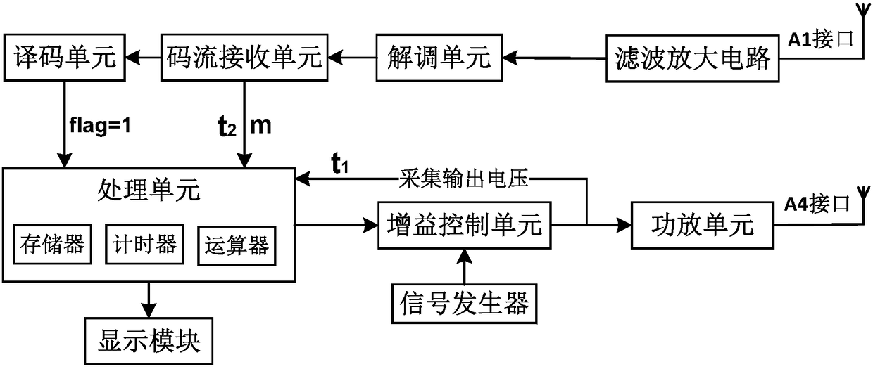
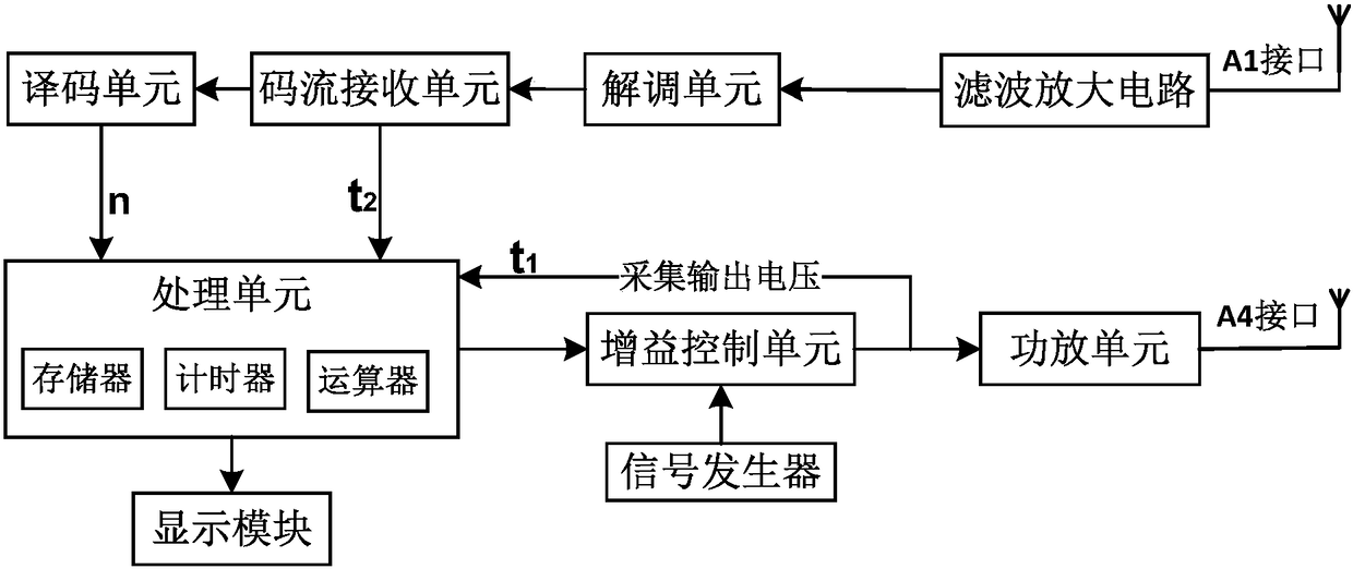
[0064] A portable transponder response time tester such as Figure 1b As shown, it includes processing unit, signal generator, gain control unit, power amplifier unit, A4 interface; A1 interface, filter amplifier circuit, demodulation unit, stream receiving unit, decoding unit; power module, display module.

[0065] The processing unit includes a timer, an arithmetic unit, and a memory, and the timer is used to record critical moments, incl...


PUM


Abstract

The invention discloses a tester and a test method for a response time of a portable transponder. The test method comprises the following steps that a processing unit compares output voltage and a starting voltage value, and when the output voltage reaches the starting voltage value, a timer records the moment as a transponder startup moment t1; when the processing unit receives a code receiving signal, the timer records the moment as a code reception start moment t2; when a decoding unit decodes a first frame of correct message, the processing unit obtains a bit number of the first frame of correct message, so that the decoding time Tr=n*T of the first frame of correct message is obtained, wherein T is a symbol cycle; and the processing unit computes to obtain an output message response time Trsp=Tr-(t1-t2) of the transponder and displays the output message response time outwards. According to the tester and the test method for the response time of the portable transponder, the output message response time of the transponder can be measured on the transponder installation scene, so that the trouble of disassembling the transponder to a laboratory to detect is avoided, and the real working condition of the transponder on the scene can be reflected.

Description

technical field [0001] The invention relates to a point transponder transmission system of a train operation control system in the field of railway communication signals, in particular to a portable transponder response time tester and a test method. Background technique [0002] The train operation signal control systems (CTCS-2 and CTCS-3) used in my country's high-speed passenger dedicated lines all rely on ground balises. The ground balise (referred to as balise) is a vehicle-ground information transmission technology that provides key line data (called messages) related to driving safety to the vehicle control device at a key position on the line to achieve automated high-speed safety. Point device for operational control. [0003] The working principle of the balise is: various line data on the ground (such as line length, slope, curve, kilometer mark, commutation point, etc.) are stored by the balise; The vehicle-mounted BTM (transponder transmission module, short f...

Claims


Application Information

Patent Timeline
Patent Type & Authority Patents(China)
IPC IPC(8): H04B17/29
CPCH04B17/29
Inventor 刘洋吕彦斌王永和刘星宇赵群张亚洲
Owner BEIJING JIAODA SIGNAL TECH
Learn More