
Pressure control for partial stroke testing

A technology of pressure control and process control, applied in general control systems, flow control, computer control, etc., can solve the problems that SIS component calibration has a strong influence and is meaningless

Active Publication Date: 2020-07-10
FISHER CONTROLS INT LLC
View PDF9 Cites 0 Cited by
  • Summary
  • Abstract
  • Description
  • Claims
  • Application Information

AI Technical Summary

Problems solved by technology

Therefore, when a SIS actuator or other SIS component is coupled to a process control device (eg, to perform a partial stroke test or other test), the bias (eg, I / P (current-to-pressure) bias of the process control device ) can have a strong effect on the calibration of SIS components
Results of tests on SIS components (eg, partial stroke tests) will be meaningless if the calibration of the SIS component deviates by a significant amount

Method used


Image

  • Pressure control for partial stroke testing
  • Pressure control for partial stroke testing
  • Pressure control for partial stroke testing

Examples


Embodiment Construction

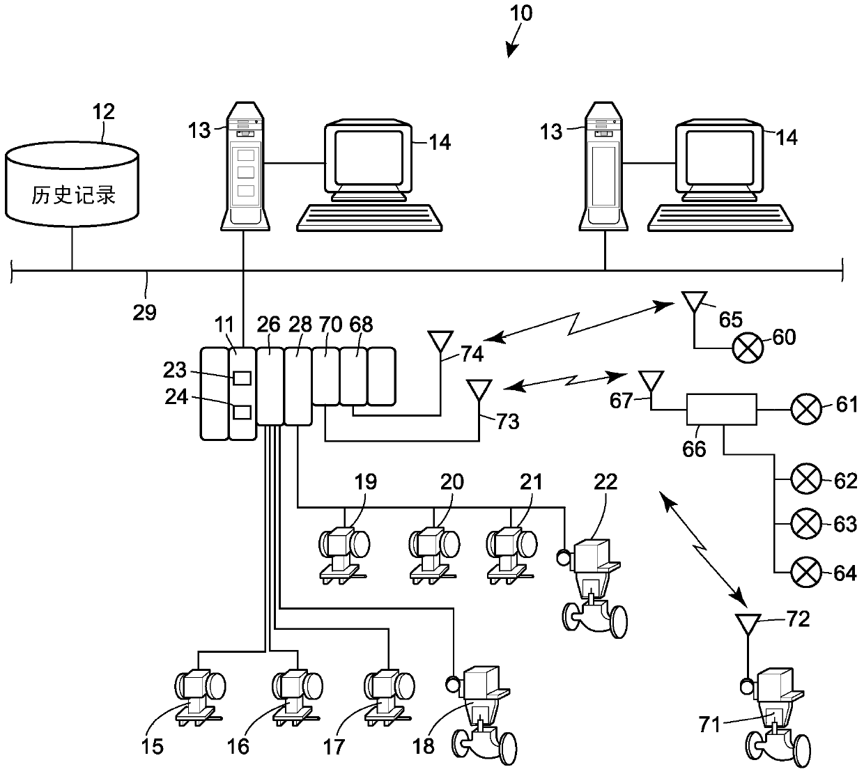
[0038] The present disclosure relates to calibrating positioners or servo controllers (eg, valve positioners) using pressure control techniques, and performing tests using pressure control techniques using positioners or servo controllers. In particular, the present disclosure relates to a method and apparatus for performing (i) by means of a constant volume, during endpoint pressure control, at the median pressure of a controlled pressure range, or during actuation at another convenient time or state of the positioner by controlling the pressure in or supplied to the actuator to determine the bias of the positioner, and (ii) by controlling the pressure in or supplied to the actuator Instead of controlling the stroke or position of the actuator to perform the test (eg, a partial stroke test). For simplicity of discussion, reference will be made throughout this description to a particular type of positioner, such as a valve positioner coupled to a slam-shut valve. In general, ...


PUM


Abstract

A method for testing a valve to control the device for coupling to control the device includes the following steps: using the process to control the pressure in the device control valve from the initial pressure to the pre -determined pressure limit;The location of the device to detect the itinerary of the valve caused by the driver; and once the pressure in the valve reaches the pre -determined pressure limit or detects one of the strokes of the valve,Back to the initial pressure.

Description

technical field [0001] The present disclosure relates to a method and apparatus for calibrating and testing a positioner, and more particularly, to a method for determining the bias of a positioner and performing a test (eg, a partial stroke test) using pressure control techniques and device. Background technique [0002] In certain industries, such as the petroleum industry, regulators are increasingly requiring partial stroke testing of emergency shut-off valves (ESVs). However, ESVs and / or other valve assemblies that are part of a "safety instrumented system" (SIS) are often designed for on / off operation and the connection between the valve stem and the actuator is not tight, resulting in significant Lost motion. Furthermore, ESVs are often characterized by high seal friction and outstanding stick-slip dynamics. All of these factors lead to poor throttle control and complicated part stroke testing. [0003] Furthermore, ESVs and / or other components of the SIS are typi...

Claims


Application Information

Patent Timeline
Patent Type & Authority Patents(China)
IPC IPC(8): G01B21/02
CPCG01B21/02F16K37/0083F15B19/00F16K37/00F15B19/005G05B15/00G05D7/00
Inventor K·W·琼克
Owner FISHER CONTROLS INT LLC
Learn More