Optical super-resolution dynamic imaging system and method based on microlens modified probe

A super-resolution, dynamic imaging technology, applied in the field of nanomanipulation, to achieve the effect of improving the efficiency and success rate, and expanding the capabilities of nanometer observation imaging and nanomanipulation

Inactive Publication Date: 2016-10-05
SHENYANG INST OF AUTOMATION - CHINESE ACAD OF SCI
View PDF4 Cites 12 Cited by
  • Summary
  • Abstract
  • Description
  • Claims
  • Application Information

AI Technical Summary

Problems solved by technology

[0004] For the above-mentioned deficiencies of the prior art, the purpose of the present invention is to provide an optical super-resolution dynamic imaging system and method based on microl

Method used


Image

  • Optical super-resolution dynamic imaging system and method based on microlens modified probe
  • Optical super-resolution dynamic imaging system and method based on microlens modified probe
  • Optical super-resolution dynamic imaging system and method based on microlens modified probe

Examples


Embodiment 1

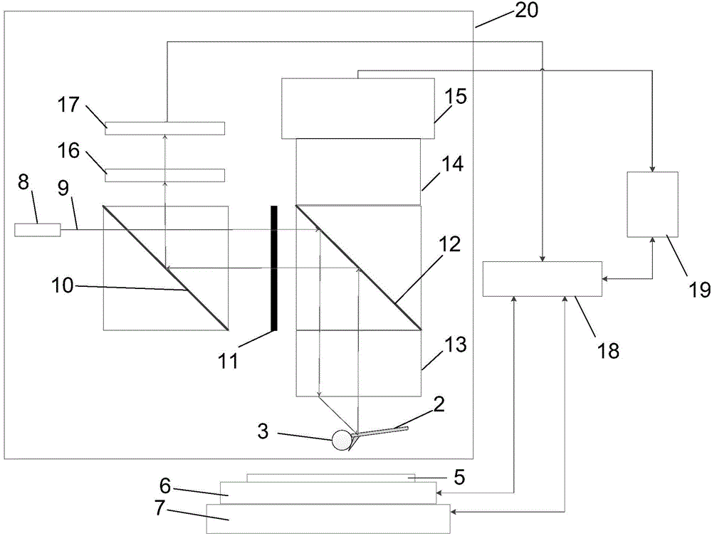
[0052] The implementation process of super-resolution optical imaging system constructed by combining microlens microscopy technology and atomic force microscopy technology is taken as an example.

[0053] Microlens Modification Probe Method:

[0054] 1) A capillary glass tube with a tapered tip, with a tip diameter of about 8 microns, is prepared by using a programmable laser puller (for example, P2000 / G, Sutter Instrument Company). The capillary glass tube is connected to the syringe through a hose and fixed on the micro-nano XYZ three-dimensional mobile platform.

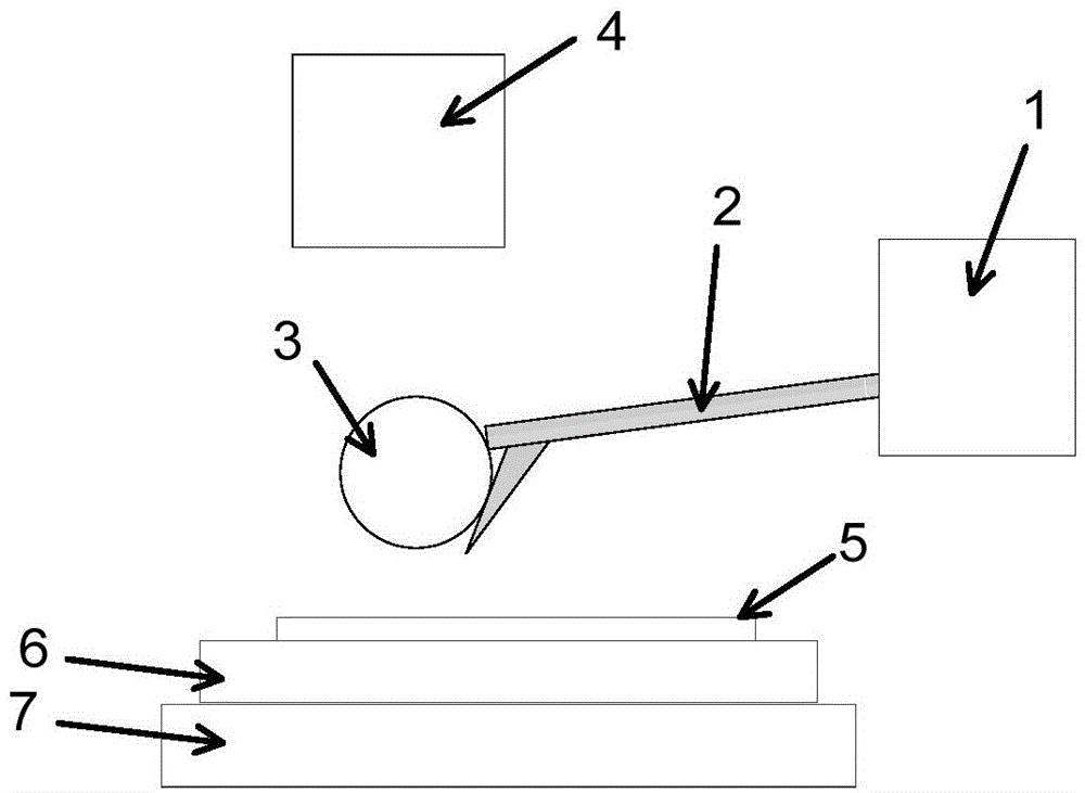
[0055] 2) Use the fixed capillary to absorb a small amount of UV-curable adhesive NOA63, and control the tip of the capillary to move to the front end of the cantilever beam of the atomic force microscope probe fixed on the probe holder through the three-dimensional mobile platform, and release a small amount of NOA63 to the front end of the cantilever beam.

[0056] 3) Take an appropriate amount of barium titan...


PUM


Abstract

The invention relates to an optical dynamic imaging system based on a microlens modified scanning probe, comprising a scanning probe microscope and a microlens; the probe of the scanning probe microscope is provided with a microlens, and the nano-positioning mechanism of the scanning probe microscope is provided with a There is a sample stage, and the optical microscope of the scanning probe microscope is located above the probe as well as the sample stage. The method includes: fixing the microlens on the probe of the scanning probe microscope; focusing the working plane of the optical microscope on the image plane of the microlens; the scanning probe microscope feeds back the position of the probe in real time, and at the same time the optical microscope obtains the position of the probe through the microlens The super-resolution images are rendered and sent to a computer for display. The invention can realize optical super-resolution dynamic observation and imaging, and effectively solve the problem of visual observation and positioning of nano-objects in the initial scanning imaging stage of scanning probe microscopes, as well as the problem of real-time visual feedback during nano-operation, thereby improving nano-observation and nano-operation s efficiency.

Description

technical field [0001] The present invention relates to a system and method of microlens-based super-resolution optical microscopy and scanning probe microscopic fusion technology, specifically utilizing the feedback control mechanism of scanning probes to realize super-resolution dynamic optical microscopy imaging, And it can realize macro, micro and nano seamless observation, as well as nano operation with real-time visual feedback. It is mainly used in fields that require nanoscale super-resolution real-time dynamic observation and operation, including materials, life sciences and other fields. Background technique [0002] At the end of the 19th century, the German scientist Ernst Abbe defined the resolution of the optical microscope, thinking that it was half the wavelength of light, that is, about 0.2 microns, which is the famous optical diffraction limit. For most of the 20th century, scientists believed that optical microscopy imaging would never break through the d...

Claims


Application Information

Patent Timeline
IPC IPC(8): G01Q60/00G01Q60/24G01N21/84
Inventor 刘连庆王飞飞于鹏李文荣刘柱王越超
Owner SHENYANG INST OF AUTOMATION - CHINESE ACAD OF SCI
Why Eureka
Try Eureka