
Combiner

A multiplexer and one-way technology, applied in the field of optical communication, can solve problems such as large cumulative offset, multiple reflection times, and incident position offset

Inactive Publication Date: 2016-10-05
HISENSE BROADBAND MULTIMEDIA TECH
View PDF11 Cites 4 Cited by
  • Summary
  • Abstract
  • Description
  • Claims
  • Application Information

AI Technical Summary

Problems solved by technology

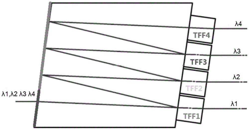
[0007] Although the above prior art realizes combining four channels of light with different wavelengths into one channel of light, there are six light reflection points in the wave combiner, the incident light λ1 has undergone six reflections, the incident light λ2 has undergone four reflections, and the incident light λ3 has undergone two reflections, and the four-way light has a total of twelve reflections, and the light has more reflections in the wave combiner
At the same time, due to the existence of errors, the angle of incidence on the high-reflection film will shift, and the angle difference between the incident light and the normal will be reflected between the reflected light and the normal, that is, how much the incident angle shifts, the reflection The angle is also offset by how much, resulting in the angular offset value of the incident light and the reflected light being twice the angle difference. Then, after multiple reflections, the cumulative offset of this angle difference will be very large, and the incident position after reflection will be A large offset occurs, which is not conducive to the merging of subsequent optical paths

Method used


Image

  • Combiner
  • Combiner
  • Combiner

Examples


Embodiment Construction

[0028] The following will clearly and completely describe the technical solutions in the embodiments of the present invention with reference to the accompanying drawings in the embodiments of the present invention. Obviously, the described embodiments are only some, not all, embodiments of the present invention. Based on the embodiments of the present invention, all other embodiments obtained by persons of ordinary skill in the art without creative efforts fall within the protection scope of the present invention.

[0029] Wavelength division multiplexing technology, especially dense wavelength division multiplexing technology, has become one of the main technologies in the field of optical communication to realize high-speed and large-capacity data transmission. In order to realize wavelength division multiplexing, it is necessary to use a multiplexer to combine multiple channels of light with different wavelengths into one channel of light.

[0030] At present, in order to r...


PUM


Abstract

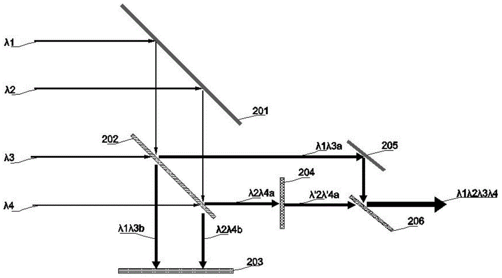
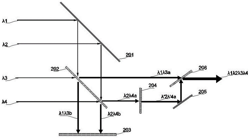
The invention provides a combiner and belongs to the optical communication field. The combiner provided by the invention is used for receiving at least four paths of light with different wavelengths which are emitted by a laser; a light path adjusting component is used for adjusting the propagation directions of the first path of light and the second path of light so as to make the first path of light and the second path of light inputted into a light separation component; the light separation component is used for separating the first path of light, the second path of light, the third path of light and the fourth path of light, combining a sub light beam obtained after separating the first path of light and a sub light beam obtaining after separating the third path of light into one path of output light, and a combining a sub light beam obtained after separating the second path of light and a sub light beam obtaining after separating the fourth path of light into one path of output light; a light beam combining component is used for combining the output light of the light separation component into one path of light; and therefore, the at least four paths of light can be combined into one path of light. Compared with the prior art, the combiner can reduce the number of reflection of light in a combining light process.

Description

technical field [0001] The invention relates to the field of optical communication, in particular to a multiplexer. Background technique [0002] Wavelength division multiplexing technology, especially dense wavelength division multiplexing technology, has become one of the main technologies in the field of optical communication to realize high-speed and large-capacity data transmission. In order to realize wavelength division multiplexing, it is necessary to use a multiplexer to combine multiple channels of light with different wavelengths into one channel of light. [0003] figure 1 A wave combiner provided for the prior art. Such as figure 1 As shown, an existing multiplexer includes a rhomboid prism, one side of the rhomboid prism is coated with an anti-reflection coating and a high-reflection coating, and the other side of the rhomboid prism is pasted with four thin film filters. Among them, the anti-reflection film increases the transmission of light, and the high-...

Claims


Application Information

Patent Timeline
IPC IPC(8): G02B27/10
CPCG02B6/2938G02B6/2706G02B6/4208G02B6/4213G02B6/4215G02B6/4244G02B27/1006G02B27/141G02B27/283G02B27/286
Inventor 陈思乡
Owner HISENSE BROADBAND MULTIMEDIA TECH
Learn More