
Self-centering clamping device adopting single-point driving mode

A self-centering clamping, single-point technology, used in positioning devices, clamping, supporting and other directions, can solve the problems of hidden safety hazards, time-consuming and laborious, and stability defects of fixed objects, and achieve the effect of strengthening stability.

Inactive Publication Date: 2016-10-12
HARBIN ENG UNIV
View PDF5 Cites 1 Cited by
  • Summary
  • Abstract
  • Description
  • Claims
  • Application Information

AI Technical Summary

Problems solved by technology

There are potential safety hazards during use, and the stability of the fixed object has certain defects. At the same time, the disassembly process of the fixed object is very troublesome, time-consuming and laborious.

Method used


Image

  • Self-centering clamping device adopting single-point driving mode
  • Self-centering clamping device adopting single-point driving mode

Examples


Embodiment Construction

[0011] The present invention will be further described below in conjunction with the accompanying drawings.

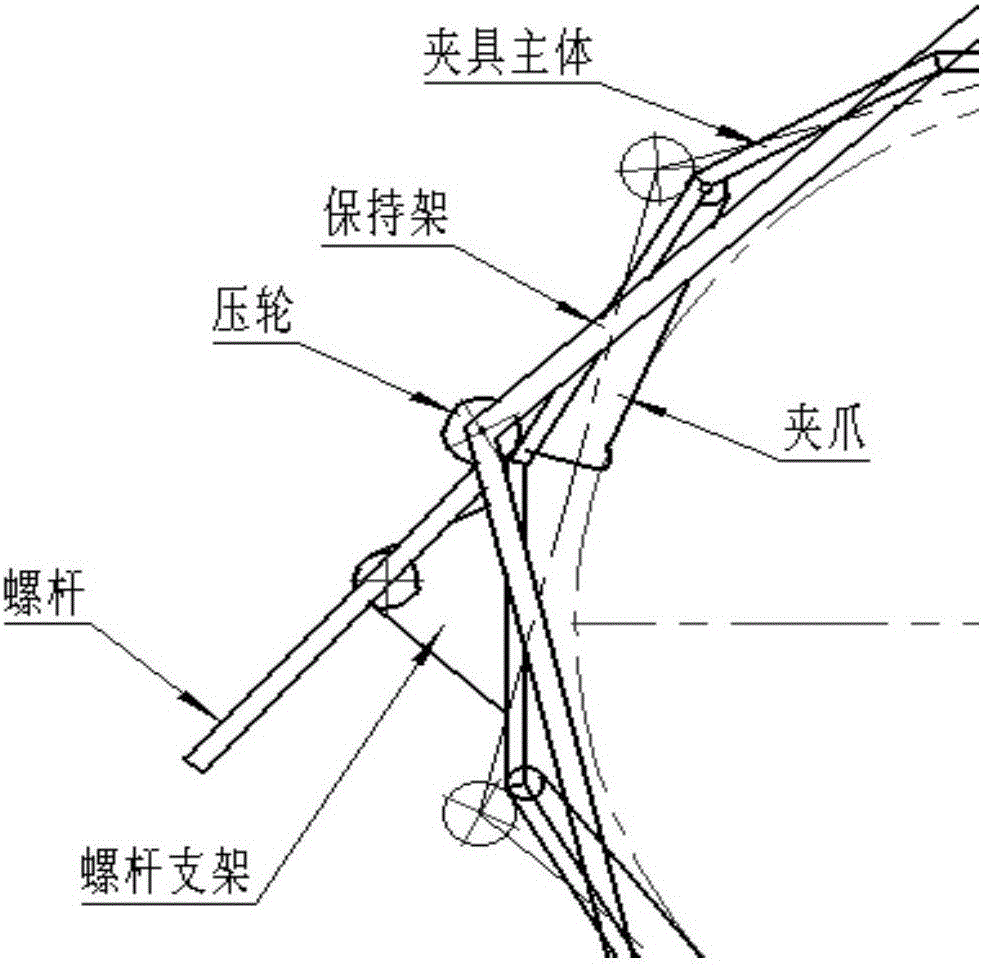
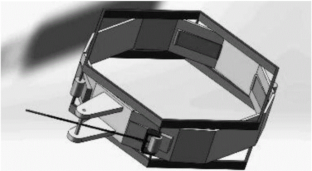
[0012] The self-centering clamping device with single-point drive is mainly composed of clamping jaws fixed on the main body of the fixture that can swing around the axis, rotatable pressure rollers installed between the upper and lower cages, cages and screws that apply driving force . When the device works, the screw rod passing through the fixed nut on the screw rod bracket is rotated, and the screw rod pulls the cage to move. The pressure roller installed on the cage, driven by the cage, moves along the outer wall of the fixture body, and presses the swingable jaws to the inside of the fixture body to complete the clamping action. Driven by the cage and acted by the four jaws, the four pressure rollers move inward at the same time to complete the clamping action and realize the self-centering function.

[0013] The device of the present invention provides a self-...


PUM


Abstract

The invention belongs to a self-centering clamping structure and the object centering and positioning field, and particularly relates to a self-centering clamping device adopting a single-point driving mode. The self-centering clamping device consists of clamping jaws fixedly arranged on ac clamp main body and capable of swinging around a shaft, rotatable pressure wheels mounted between an upper holding frame and a lower holding frame, the holding frames and a screw for applying driving force, wherein the screw passes through a fixed nut on a screw bracket and then is fixed to a ring-shaped clamp main body; one end of the screw is pressed below the rotatable pressure wheels mounted between the upper holding frame and the lower holding frame; and wedge-shaped clamping jaws capable of swinging around the shaft are further mounted on the clamp main body below the pressure wheels. According to the self-centering clamping device adopting the single-point driving mode, the four pressure wheels are driven by the holding frames to act with the four clamping jaws, and move inwards, so that clamping action is completed and self-centering can be realized, and therefore, fixing stability can be further strengthened.

Description

technical field [0001] The invention belongs to the field of self-centering clamping structure and object centering positioning, and in particular relates to a self-centering clamping device driven by a single point. Background technique [0002] General object clamping is usually achieved by multiple fastening screws, and eccentricity often occurs during the clamping process. There are potential safety hazards during use, and the stability of the fixed object has certain defects. At the same time, the disassembly process of the fixed object is very troublesome, time-consuming and laborious. Therefore, it is necessary to redesign a new type of clamping structure, which can realize the automatic centering function while realizing the clamping of the object. Contents of the invention [0003] The purpose of the present invention is to provide a self-centering clamping structure with single-point drive, which can achieve better clamping effect, and can ensure the self-center...

Claims


Application Information

Patent Timeline
Patent Type & Authority Applications(China)
IPC IPC(8): B23Q3/00
CPCB23Q3/00
Inventor 蔡成涛张传彬朱齐丹翁翔宇范冰王立辉栗蓬
Owner HARBIN ENG UNIV
Learn More