
A self-centering chuck and cutting device for cutting square tubes

A self-centering and collet technology, applied in welding equipment, laser welding equipment, metal processing equipment, etc., can solve the problems of complex fixture structure, bulky volume, high manufacturing cost, etc., and achieve wide application range, miniaturized structure size, The effect of low cost

Inactive Publication Date: 2018-01-02
UNIV OF JINAN
View PDF8 Cites 0 Cited by
  • Summary
  • Abstract
  • Description
  • Claims
  • Application Information

AI Technical Summary

Problems solved by technology

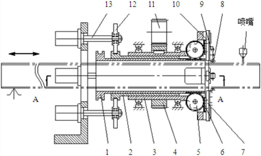
[0003] In order to solve the problems of complex structure, bulky fixture and high manufacturing cost in the prior art, the present invention discloses a self-centering chuck for cutting square pipes and a cutting device. The present invention uses an air cylinder as the driving device, and the position of the air cylinder is not fixed. Change, no need to use rotary joints, this chuck is used for laser cutting pipes, it can clamp the workpiece to rotate, and the radial displacement of the 2 pairs of jaws is automatically centered, clamping or loosening the workpiece

Method used


Image

  • A self-centering chuck and cutting device for cutting square tubes
  • A self-centering chuck and cutting device for cutting square tubes

Examples


Embodiment 1

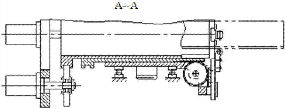
[0033] The self-centering chuck for cutting square tubes includes an inner sleeve, an outer sleeve and a hollow main shaft installed coaxially from the inside to the outside. The axis rotates; on the outer cylindrical surface of the inner sleeve and the outer sleeve, one end is respectively connected to a driving cylinder that drives it to move along the axis of the hollow main shaft, and the other end is respectively meshed with a transition gear, and the transition gear is fixed on the hollow main shaft , rotates synchronously with the hollow main shaft; at the same time, the transition gear meshes with the rack mounted on the slide plate, the slide plate is installed in the radial direction of the hollow main shaft, perpendicular to the axial direction of the hollow main shaft, and the tooth The axial direction of the bars is also perpendicular to the axial direction of the hollow main shaft. And a clamping device for clamping the workpiece is installed on the slide plate; ...

Embodiment 2

[0054] A square pipe cutting device, comprising the self-centering chuck described in Embodiment 1.


PUM


Abstract

The invention discloses a self-centering chuck for square pipe cutting and a cutting device. The self-centering chuck comprises an inner sleeve, an outer sleeve and a hollow spindle, wherein the inner sleeve, the outer sleeve and the hollow spindle are coaxially mounted in sequence from inside to outside. The inner sleeve is in clearance fit with the outer sleeve, and the outer sleeve is in clearance fit with the hollow spindle. The hollow spindle is driven by a driving device to rotate along the axis of the hollow spindle. One end of the outer cylindrical surface of the inner sleeve is connected with driving air cylinders driving the inner sleeve to move in the axis direction of the hollow spindle, and the other end of the outer cylindrical surface of the inner sleeve is engaged with transition gears; one end of the outer cylindrical surface of the outer sleeve is connected with driving air cylinders driving the outer sleeve to rotate in the axis direction of the hollow spindle, and the other end of the outer cylindrical surface of the outer sleeve is engaged with transition gears; and the transition gears are fixed to the hollow spindle and synchronously rotate along with the hollow spindle. Meanwhile, the transition gears are engaged with racks, the racks are mounted in the radial direction of the hollow spindle and are perpendicular to the axis direction of the hollow spindle; and the racks drive sliding plates connected with the racks to move in the radial direction of the hollow spindle, and clamping devices used for clamping workpieces are mounted on the sliding plates.

Description

technical field [0001] The invention relates to a square pipe cutting device, in particular to a self-centering chuck and a cutting device for cutting square pipes. Background technique [0002] When using a laser cutting machine to punch holes on long rectangular pipes, cut special-shaped surfaces or cut off blanks, the pipes must have two chucks to work together, and there is a dead chuck at the end of the workpiece to clamp the workpiece, and the feed system makes the length of the workpiece Servo feeding, the chuck has unlimited freedom of rotation and can rotate freely; in the cutting work area, it is also required to have a movable self-centering chuck, which drives the workpiece to rotate with its own power, and clamps the workpiece during cutting. When the feed movement is required, the clamping mechanism needs to be released, and when the workpiece is moved in place, the workpiece is clamped again and can be centered automatically. Since the clamping mechanism rota...

Claims


Application Information

Patent Timeline
Patent Type & Authority Patents(China)
IPC IPC(8): B23K26/70
CPCB23K26/702
Inventor 侯志坚宋强
Owner UNIV OF JINAN
Learn More