Engine cylinder wedge-shaped centering clamp

A technology for engine cylinder blocks and centering fixtures, applied in clamping, positioning devices, manufacturing tools, etc., can solve the problems of uncontrollable positioning, the inability to truly determine the center of the cylinder liner hole, and the inability to ensure the consistency of the B reference, etc., to eliminate Tolerance, uniform finishing allowance, avoiding unilateral effect

Pending Publication Date: 2018-06-12
RUIQING AUTOMOBILE ENGINE TECH
View PDF0 Cites 0 Cited by
  • Summary
  • Abstract
  • Description
  • Claims
  • Application Information

AI Technical Summary

Problems solved by technology

However, in actual production, due to the accuracy of the blank, the diameter and position accuracy of the cylinder liner cannot be guaranteed to be consistent.
In this case, the above-mentioned two-point positioning method cannot really determine the center of the cylinder bore, and furthermore, the consistency of the B reference cannot be guaranteed. At this time, the positioning will be uncontrollable

Method used


Image

  • Engine cylinder wedge-shaped centering clamp
  • Engine cylinder wedge-shaped centering clamp
  • Engine cylinder wedge-shaped centering clamp

Examples


Embodiment 1

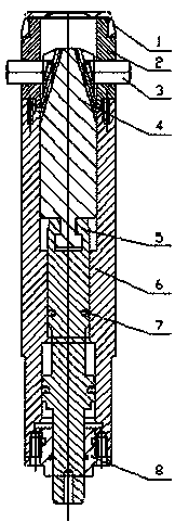
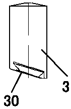
[0019] Such as Figures 2 to 5 A wedge-shaped centering fixture for an engine block shown includes a guide sleeve with a main guide hole and a positioning mechanism that is matched and connected with the guide sleeve. The positioning mechanism includes more than three positioning slide chucks 3 and each positioning The sliding part of the transmission connection of the sliding chuck 3; the positioning sliding chuck 3 is arranged radially in the positioning guide hole on the side of the guiding sleeve, the sliding part is arranged in the main guiding hole of the guiding sliding sleeve, and the shafts of each positioning guiding hole The direction is in the same plane perpendicular to the axial direction of the main guide hole; the tails of each positioning sliding chuck 3 are connected with a plurality of dovetail grooves 40 on the slider in one-to-one correspondence, and the dovetail grooves 40 are relatively connected to the main guide hole. The axial direction is inclined, a...

Embodiment 2

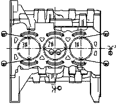
[0027] Such as Figures 6 to 7 , a positioning device for an engine block, comprising a clamp body 9, the clamp body 9 is provided with two positioning holes 10 corresponding to the cylinder liner on the engine block 11, and the wedge-shaped positioning of the engine block as described above is arranged in the positioning holes 10. centering fixture, the centering fixture is connected with the upper surface of the clamp body 9 through the reference end surface of the fixed base 6, and the lower end of the sliding seat pull rod 5 of the centering fixture runs through the positioning hole and is connected with a power mechanism; the upper surface of the clamp body 9 is also set There are a plurality of positioning bosses 12 for supporting the engine block 11, and the upper parts of the plurality of positioning bosses 12 are in the same plane parallel to the reference end surface of the centering fixture.

[0028] The engine block 11 is positioned by the bottom surface and the tw...


PUM


Abstract

The invention relates to an engine cylinder wedge-shaped centering clamp. The engine cylinder wedge-shaped centering clamp comprises a guiding sliding sleeve with a main guiding hole, and a positioning mechanism which is connected with the guiding sliding sleeve in a matched manner. The positioning mechanism comprises three or more positioning sliding clamping heads and sliding pieces which are intransmission connection with the positioning sliding clamping heads. The positioning sliding clamping heads are arranged in positioning guiding holes in the side portion of the guiding sliding sleevein the radial direction, the sliding pieces are arranged in the main guiding hole of the guiding sliding sleeve, and the axial directions of the positioning guiding holes are located in the same plane perpendicular to the axial direction of the main guiding hole. The tails of the positioning sliding clamping heads are connected with a plurality of dovetail grooves in the sliding pieces in a one-to-one corresponding fit manner. The dovetail grooves are obliquely arranged relative to the axial direction of the main guiding hole, and the inclination angles of the dovetail grooves are consistent.The guiding sliding sleeve is provided with a standard end face perpendicular to the axial direction of the main guiding hole. According to the scheme, air cylinder sleeve self-centering can be achieved, errors are eliminated to the maximum degree, it is guaranteed that the later air cylinder sleeve finish machining allowance is uniform, and single sides are avoided.

Description

technical field [0001] The invention relates to a wedge-shaped centering fixture for an engine cylinder, belonging to the technical field of conveying equipment. Background technique [0002] In the production and processing stage of the automobile engine cylinder block, some processes need to use the bottom surface of the cylinder block and the cylinder liner hole to position and process the fine reference. The cylinder liner is embedded in the cylinder block during casting, and its dimensional accuracy and position accuracy have certain errors, and the consistency cannot be guaranteed, which puts forward higher requirements for the positioning fixture. The existing positioning method generally restricts the degree of freedom of the cylinder block respectively through three cylinder holes, and each cylinder hole adopts two positioning points. This positioning method cannot eliminate the position error caused by the casting inlay of the cylinder liner, which may lead to une...

Claims


Application Information

Patent Timeline
IPC IPC(8): B23Q3/06
CPCB23Q3/062
Inventor 郭万山王萌彬周峰周伟赵辉秦阳阳刘志奎李龙
Owner RUIQING AUTOMOBILE ENGINE TECH
Why Eureka
Try Eureka