Intelligent tool fault diagnosis method

A fault diagnosis and cutting tool technology, which is applied in the direction of manufacturing tools, metal processing machinery parts, measuring/indicating equipment, etc., can solve problems affecting production efficiency, consuming economic costs, and cutting tool fault diagnosis is not online and intelligent.

Inactive Publication Date: 2016-10-12
BEIJING INFORMATION SCI & TECH UNIV
View PDF5 Cites 16 Cited by
  • Summary
  • Abstract
  • Description
  • Claims
  • Application Information

AI Technical Summary

Problems solved by technology

[0002] At present, tool fault diagnosis is carried out by regularly unloading the tool and observing with the naked eye, and judging whether the tool is seriously worn according to the shape of the tool and the experience...

Method used


Image

  • Intelligent tool fault diagnosis method
  • Intelligent tool fault diagnosis method
  • Intelligent tool fault diagnosis method

Examples


Embodiment Construction

[0036] The present invention will be described in detail below with reference to the drawings and embodiments.

[0037] The present invention provides an intelligent tool fault diagnosis method, which includes the following steps:

[0038] 1) Set up a PLC between the CNC end of the machine tool (computer numerical control end) and the machine tool end, and the PLC realizes the input and output signal processing on the machine tool side and the CNC side.

[0039] 2) The PLC obtains several tool vibration signals x(t) generated during the machining process of the machine tool, and processes the collected tool vibration signals x(t) and extracts the tool characteristics:

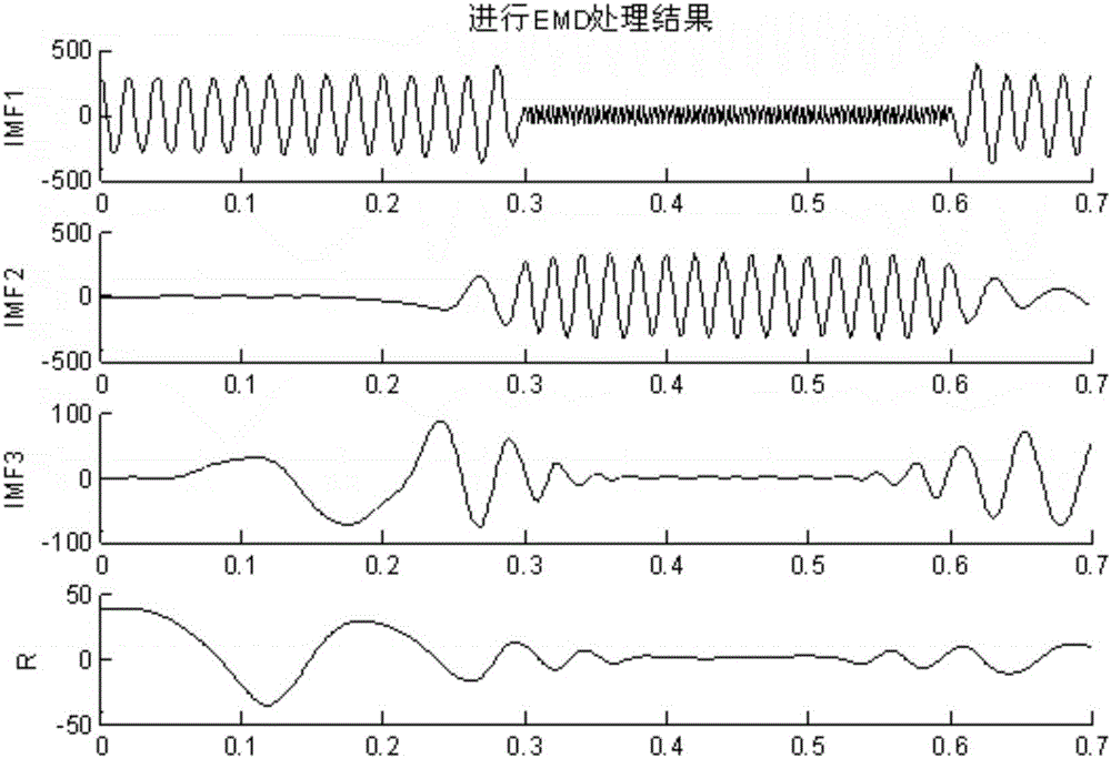
[0040] 2.1) Empirically decompose the collected tool vibration signal x(t), and decompose the fluctuations or trends of different scales in the tool vibration signal x(t) step by step to generate data sequences with different characteristic scales, and combine These sequences are defined as intrinsic mode functions (IM...


PUM


Abstract

The invention relates to an intelligent tool fault diagnosis method. The intelligent tool fault diagnosis method comprises the steps that a PLC is arranged between the CNC end of a machine tool and the machine tool end; a plurality of tool vibration signals x(t) produced in the machine tool machining process are obtained by the PLC, all the collected tool vibration signals x(t) are processed, and tool characteristics are extracted; the correspondence relation between the tool vibration signals and a tool abrasion fault is built according to the obtained tool characteristic information so that the tool abrasion fault can be intelligently identified; each tool vibration signal is trained to obtain a hidden Markov model lambda; and the likelihood ratios are calculated through the trained hidden Markov models lambda, the sequences O of the tool vibration signals are input into all the trained hidden Markov models, the likelihood ratio of each tool vibration signal under the corresponding hidden Markov model is obtained, and then the tool state is identified. According to the intelligent tool fault diagnosis method, the characteristics of the machine tool and the characteristics of the vibration signals in the tool machining process are combined, the tool abrasion fault is automatically detected, and the tool abrasion state can be automatically identified.

Description

Technical field [0001] The invention relates to a tool fault diagnosis method, in particular to an intelligent tool fault diagnosis method used in the field of testing instruments. Background technique [0002] At present, the tool fault diagnosis is performed by unloading the tool on a regular basis, and it is judged whether the tool is severely worn according to the tool shape and the experience of the operator. Such tool fault diagnosis is not linear and intelligent, and it takes a lot of money. Labor cost, if tool diagnosis is frequently performed, it will also affect production efficiency and consume economic costs. Summary of the invention [0003] In view of the above problems, the purpose of the present invention is to provide an intelligent tool fault diagnosis method, which combines the characteristics of the machine tool and the vibration signal characteristics of the tool processing to realize automatic detection of tool wear faults and automatically identify the tool ...

Claims


Application Information

Patent Timeline
IPC IPC(8): B23Q17/09
CPCB23Q17/0957
Inventor 黄民高延吴国新孙巍伟马超
Owner BEIJING INFORMATION SCI & TECH UNIV
Why Eureka
Try Eureka