Mechanism-data fusion driven variable working condition tool wear state monitoring method

A tool wear and state technology, applied in the direction of manufacturing tools, metal processing equipment, measuring/indicating equipment, etc., can solve the problems of difficult installation of dynamometer, low monitoring accuracy, limited cost, etc.

Active Publication Date: 2022-03-01
XI AN JIAOTONG UNIV
View PDF10 Cites 1 Cited by
  • Summary
  • Abstract
  • Description
  • Claims
  • Application Information

AI Technical Summary

Problems solved by technology

[0009] To sum up, the online monitoring method of tool wear status under variable milling conditions in the prior art has the following problems: the data is difficult to disting

Method used


Image

  • Mechanism-data fusion driven variable working condition tool wear state monitoring method
  • Mechanism-data fusion driven variable working condition tool wear state monitoring method
  • Mechanism-data fusion driven variable working condition tool wear state monitoring method

Examples


Example Embodiment

[0072] Example 1

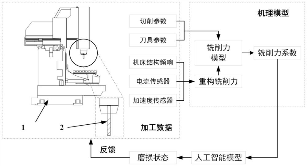
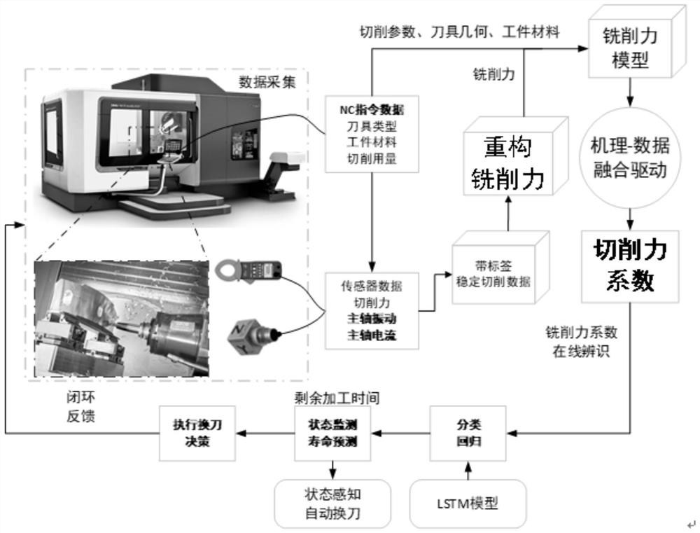
[0073] Mechanism model and machining data fusion tool wear condition monitoring method, such as figure 2 As shown, including the following steps:

[0074] Step 1) Synchronize the spindle vibration signal, current signal, and NC command data, the NC command data includes a tool name and milling parameters;

[0075] Step 2) Take the tool tag for the main shaft vibration signal and the spindle motor current signal of the tool different milling time in the tool name, the milling parameters, respectively;

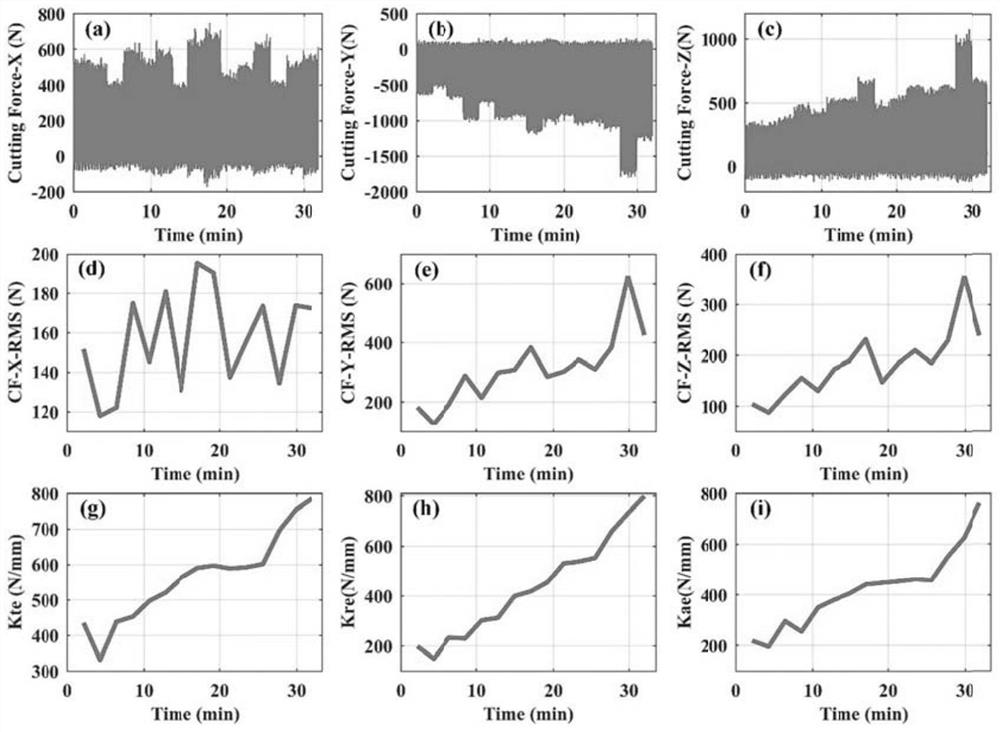
[0076] Step 3) Access the spindle acceleration and the spindle motor current signal, based on the spindle acceleration and the spindle motor current signal reconstruction milling force, further calculate the milling force coefficient;

[0077] Step 4) Based on the milling force coefficient, the regression model is established by depth learning, based on the regression model, the tool wear status identification and the remaining life prediction;

[0078] Step 5) Ge...

Example Embodiment

[0080] Example 2

[0081] Combine figure 1 and figure 2, By the acceleration sensor attached to the main shaft near the shank position, the spindle vibration signal is collected, the spindle motor current signal (obvious to the electric spindle effect) is collected by a low-pass filter processing reconstruction milling force. . The key steps are as follows: The key steps are as follows:

[0082] Step (1): Data Synchronous Collection: By acceleration signal, current signal reconstruct the milling force, and thus linear regression is obtained by the milling force coefficient. It is necessary to implement machine tool external sensor data synchronous acquisition, and sensor data includes spindle vibration signals, current signals, NC command data refers to spindle rotation speed, feed speed, X / Y / Z axis coordinate, tool teeth, tool name, etc. information. The external sensor data collects through the data acquisition system, and the NC command data reads from the Siemens CNC syste...

Example Embodiment

[0126] Example 3

[0127] Mechanism model and machining data fusion tool wear condition monitoring system, including:

[0128] The data acquisition unit is used to synchronize the spindle vibration signal, current signal, and NC command data;

[0129] The time series correspondence unit, intersecting the data acquisition unit, for use in a tool name, milling parameter as a label, respectively, the main shaft vibration signal and the current signal of the tool different milling time, respectively;

[0130] The milling force reconstruction unit is interspersed with the time series corresponding unit to acquire the spindle acceleration and the spindle motor current signal. Based on the spindle acceleration and the spindle motor current signal reconstruction milling force, the milling force coefficient is further calculated, and the milling force coefficient Identify.

[0131] Wear state identification unit, intersecting the milling force reconstruction unit, for use in milling force ...


PUM


Abstract

The invention discloses a mechanism-data fusion driven variable working condition tool wear state monitoring method, and belongs to the field of machine tool state monitoring. A spindle acceleration signal and a spindle motor current signal are used for reconstructing cutting force to replace a dynamometer to obtain the cutting force, the reconstructed milling force is used for replacing theoretical milling force, and the reconstructed milling force and working condition information serve as models to be input into an instantaneous milling force mechanism model. High-dimensional sensor data are cut and segmented through low-dimensional data such as cutter names and cutting parameters, cutter wear state monitoring and remaining service life prediction under variable working conditions are achieved, and the problem that an existing cutter wear state monitoring system can only be suitable for fixed cutting working conditions is solved. According to the method, the wear degradation state of the milling cutter is monitored by fully exerting the advantages of a mechanism model and a data driving method, the proposed tool wear state monitoring can meet the requirements of different machining working conditions, and the method has high engineering application value.

Description

technical field [0001] The invention belongs to the field of numerical control cutting and processing, and relates to a mechanism-data fusion-driven tool wear state monitoring method under variable working conditions. Background technique [0002] At present, in the cutting process of CNC machine tools, the judgment of tool wear failure status and tool replacement mainly rely on the experience of workers. This tool change strategy hinders the development of unmanned production lines. In the process of tool wear and degradation, if the replacement is not timely, the size of the parts will be out of tolerance, or even the parts will be scrapped, and the cost will increase; frequent tool replacement will cause excessive downtime and affect production efficiency, and the tool life cannot be fully utilized, increasing production costs. With the continuous development of unattended intelligent production lines, automatic tool replacement strategies based on condition monitoring ha...

Claims


Application Information

Patent Timeline
IPC IPC(8): B23Q17/09
CPCB23Q17/0957
Inventor 张俊白乐乐潘天航李超唐宇阳赵万华
Owner XI AN JIAOTONG UNIV
Why Eureka
Try Eureka