Visual centralized monitoring system for loading videos of dynamic machine rooms

A centralized monitoring and computer room technology, applied in the direction of electrical program control, comprehensive factory control, etc., can solve problems such as failure to analyze fault sources, lack of alarm information filtering, intelligent correlation analysis, and unfavorable fault point search

Active Publication Date: 2013-04-17
JIANGSU ELECTRIC POWER CO +2
View PDF8 Cites 50 Cited by
  • Summary
  • Abstract
  • Description
  • Claims
  • Application Information

AI Technical Summary

Problems solved by technology

[0006] 2. The existing automated computer room monitoring system lacks cross-system information sharing, lacks comprehensive analysis and processing of alarms from environmental equipment and business systems in each computer room, and cannot analyze the real source of failure
[0007] 3. The existing automatic computer room monitoring system only pays attention to the access of alarm information, lacks filtering of alarm information and intelligent correlation analysis, which is not conducive to maintenance personnel to find fault points
[0008] 4. The existing automated machine room monitoring system only adopts static model rendering for the modeling of the machine room, and cannot correspond to it when the real environment changes

Method used


Image

  • Visual centralized monitoring system for loading videos of dynamic machine rooms
  • Visual centralized monitoring system for loading videos of dynamic machine rooms
  • Visual centralized monitoring system for loading videos of dynamic machine rooms

Examples


Embodiment Construction

[0038] The present invention will be described more fully hereinafter with reference to the accompanying drawings, in which exemplary embodiments of the invention are illustrated.

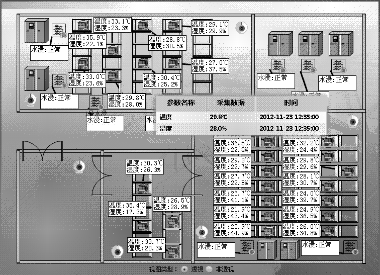
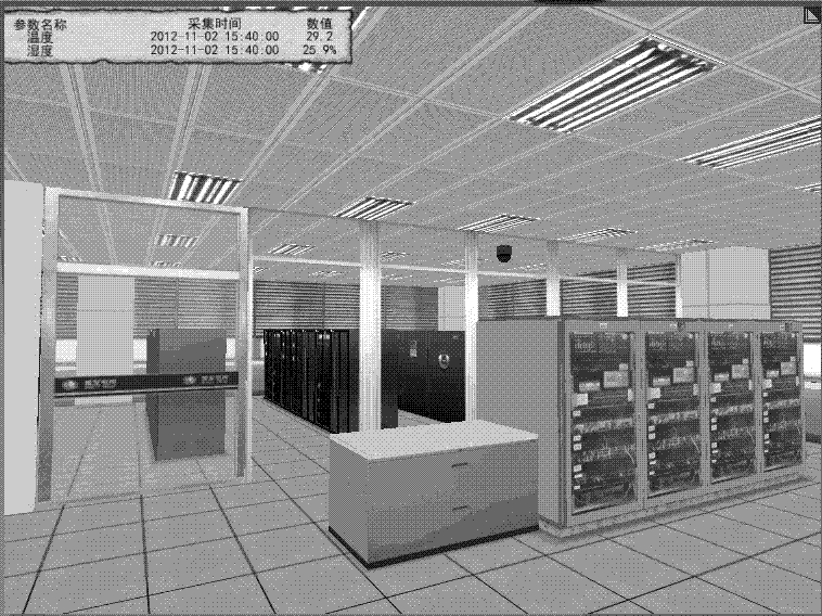
[0039] Such as figure 1 As shown, the visualized centralized monitoring system for dynamic computer rooms carrying video provided by the present invention mainly includes a plurality of automated computer rooms 1-N located in different locations and a client 2 .

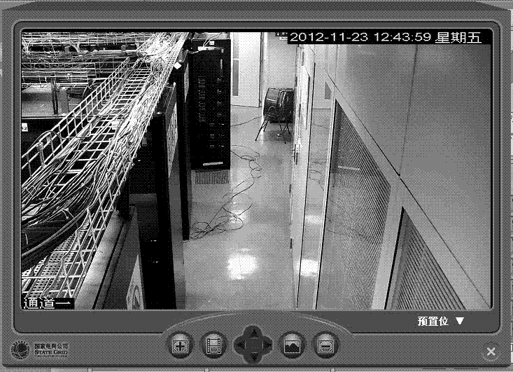
[0040] Acquisition servers and cameras are set in each of the computer rooms, such as figure 1 As shown, an acquisition server 10 and a camera 11 are set in the automation machine room 1, and an acquisition server N0 and a camera N1 are set in the automation machine room N. The acquisition server includes a plurality of sensors, and the plurality of sensors are used to collect parameters of environmental equipment in the computer room (such as air conditioners, etc.) and various business systems (such as OPEN300 system, electric energy s...


PUM


Abstract

The invention discloses a visual centralized monitoring system for loading videos of dynamic machine rooms. The system comprises a client and a plurality of automatic machines rooms in different places, wherein each machine room is provided with an acquisition server and a camera. The automatic machine rooms are managed in a centralized way through the centralized dynamic modeling configuration of the automatic machine rooms, and equipment acquisition and warning messages are bound to model elements synchronously, operation states and warning conditions of the automatic machine rooms are displayed intuitively through a Unity3D technology and an FELX technology, so that uniform configuration and uniform monitoring of the automatic machine rooms are realized. Meanwhile, in order to remedy the defect that the automatic machine rooms are still artificial, the video monitoring technology is utilized to realize the remote control of the real operation conditions in any position of the automatic machine rooms, thereby avoiding the irregular inspection of a watchman in each machine room, and truly realizing the centralized management and monitoring of the automatic machine rooms by the watchman.

Description

technical field [0001] The invention relates to the technical field of automatic computer room monitoring, in particular to a visual centralized monitoring system for a dynamic computer room carrying video. Background technique [0002] The computer room is a place that provides an operating environment for various electronic information equipment used for electronic information processing, storage, and exchange to complete the information processing process. Once the auxiliary equipment in the computer room environment fails, the parameters such as power, temperature and humidity, and fresh air will deviate from the normal value, which will directly affect the normal operation of the computer system and pose a threat to the reliability of data transmission and storage. If the accident is serious and cannot be dealt with in time, it may damage the hardware equipment and cause serious consequences. [0003] Today's electric power information enterprises are developing rapidl...

Claims


Application Information

Patent Timeline
Patent Type & Authority Applications(China)
IPC IPC(8): G05B19/418
Inventor 张龙苏大威张国江张斌郑海雁官国飞夏卫进徐田曾飞陈玉权
Owner JIANGSU ELECTRIC POWER CO
Why Eureka
Try Eureka