Linkage laminated injection mold

An injection mold and lamination technology, applied in the field of linkage lamination injection mold, can solve the problems of low efficiency, high cost and high operating cost

Inactive Publication Date: 2016-10-12
NINGBO SHUANGLIN MOULD CO LTD
View PDF7 Cites 2 Cited by
  • Summary
  • Abstract
  • Description
  • Claims
  • Application Information

AI Technical Summary

Problems solved by technology

The cavity of the three-plate mold is set at the fixed mold, and the core is set at the movable mold. The three-plate mold is suitable for injection molding products with simple structure and small shape. For products with large shapes, such as side cover products of automobile airbags, if using The three-plate mold will increase the area of ​​the parting surface of the mold. If the parting surface is large, a large-sized injection molding machine is required for the application of the mold. The larger the specification of the injection molding machine, the higher the operating cost, and the operating cost is allocated to In terms of products, the cost of products is high; if a small-sized injection molding machine that can only be matched with two-plate molds is used for multi-machine production, the production efficiency will be low, and the overall production cost of products will be higher than that of three-plate molds. Therefore, the existing The technology has the problems and deficiencies of high cost and low efficiency

Method used


Image

  • Linkage laminated injection mold
  • Linkage laminated injection mold
  • Linkage laminated injection mold

Examples


Embodiment Construction

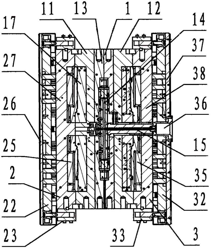
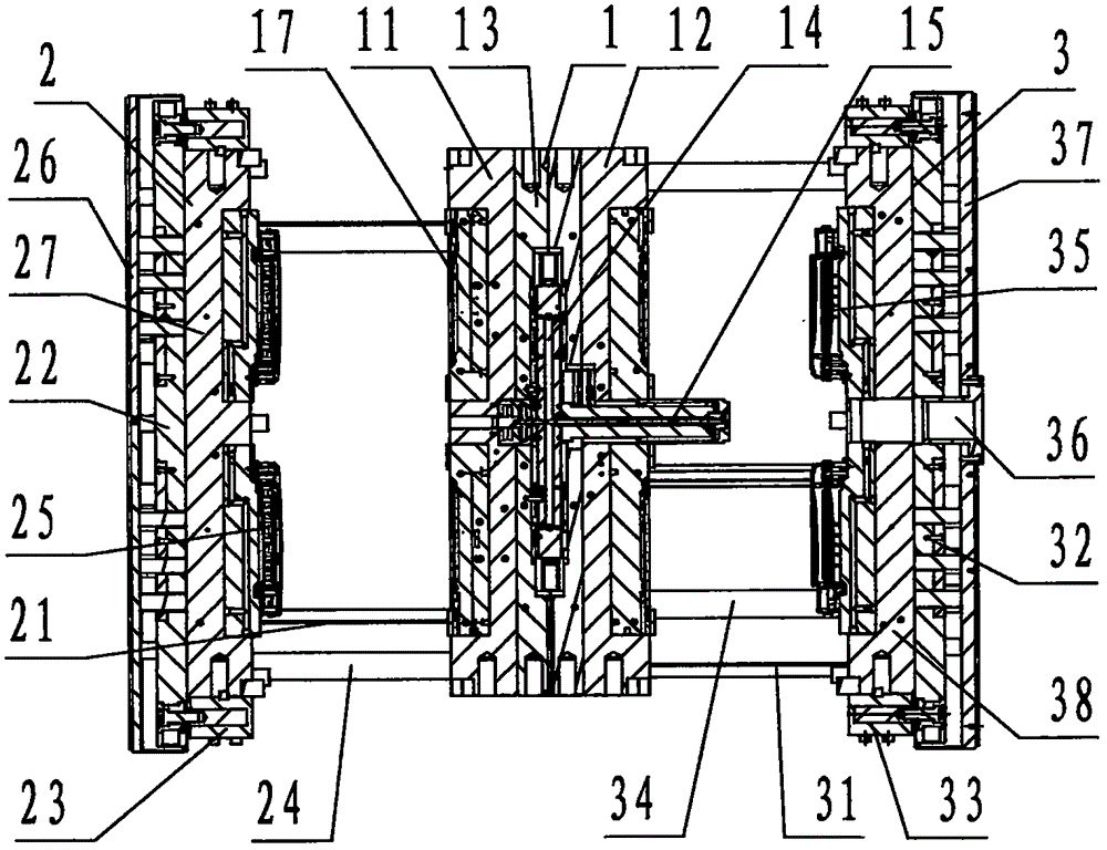
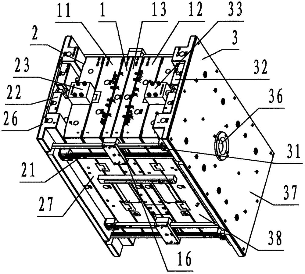
[0026] Refer to Figure 1 ~ Figure 4 , A linked laminated injection mold of the present invention includes a middle cavity template 1, a left core template 2, a right core template 3, wherein: the middle cavity template 1 is, in order from left to right, and is called A The cavity carrier board 11, the thermal fluid carrier board 13, and the B cavity carrier board 12 are fixedly connected and constituted by three rectangular plate-shaped steel members; wherein, the left side of the A cavity carrier board 11 is provided with two product cavities 17; The right side of the B cavity carrier plate 12 is provided with two product cavities 17; the center of the heat flux carrier plate 13 is provided with a cylindrical shape that passes through the B cavity carrier plate 12 and protrudes to the right Two cavities 17 connecting the sliding hot gate 15 and the A cavity carrier plate 11 and two cavities 17 of the B cavity carrier plate 12 are also provided inside the hot fluid carrier pla...


PUM


Abstract

The invention discloses a linkage laminated injection mold which comprises a middle cavity mold plate (1), a left core mold plate (2) and a right core mold plate (3), wherein the adopted left and right core mold plates are respectively positioned on the left and right sides of the middle cavity mold plate; the middle cavity mold plate is provided with an A cavity carrier plate, a B cavity carrier plate and a heat flow carrier plate; two mold cavities are formed in each of the A cavity carrier plate and the B cavity carrier plate; the heat flow carrier plate is provided with a head flow distributing channel, a sliding hot sprue and linkage gears; the left core mold plate is provided with a left rack, a left top plate, a left ejector oil cylinder, a left guide column, a left mold core, a left bottom plate and a left carrier plate; and the right core mold plate is provided with a right rack, a right top plate, a right ejector oil cylinder, a right guide column, a right mold core, a sprue hole, a right bottom plate and a right carrier plate. According to the linkage laminated injection mold, a laminated structure that two parting surfaces are arranged on the left and right sides of the middle cavity mold plate is adopted, and a technical scheme that four products can be simultaneously produced by adopting one mold through linkage opening-closing of the left rack, the right rack and the linkage gears, thereby achieving the injection molding production of auto airbag side cover products, and fulfilling the purposes of cost reduction and efficiency improvement.

Description

Technical field [0001] The invention relates to an injection mold, in particular to a linkage laminated injection mold used for injection molding of automobile safety airbag side cover products, one mold with four outputs and a mechanical linkage opening and closing laminated structure. Background technique [0002] In the prior art, the injection mold of one mold and one product adopts a two-plate mold structure, and the injection mold of one mold with multiple products adopts a three-plate structure with a stripper at the fixed mold, referred to as a three-plate mold; injection molding is to improve efficiency and reduce products Cost, tend to use more than one mold as much as possible. The cavity of the three-plate mold is set at the fixed mold, and the core is set at the movable mold. The three-plate mold is suitable for injection products with simple structure and small body. For larger products, such as automobile airbag side cover products, if used The three-plate mold wi...

Claims


Application Information

Patent Timeline
Patent Type & Authority Applications(China)
IPC IPC(8): B29C45/32
CPCB29C45/32
Inventor 顾来法胥树志储吉江李诚枫袁贤飞
Owner NINGBO SHUANGLIN MOULD CO LTD
Why Eureka
Try Eureka