Fixing clip and fixing structure for fixing a member to be installed using the fixing clip
A technology for installing components and fixing clips, applied in the direction of connecting components, threaded fasteners, detachable fasteners for friction clamping, etc., can solve the problem of increasing the cross-sectional area of the leg, and achieve the effect of increasing the pull-out load
- Summary
- Abstract
- Description
- Claims
- Application Information
AI Technical Summary
Problems solved by technology
Method used
Image

Examples
no. 1 example
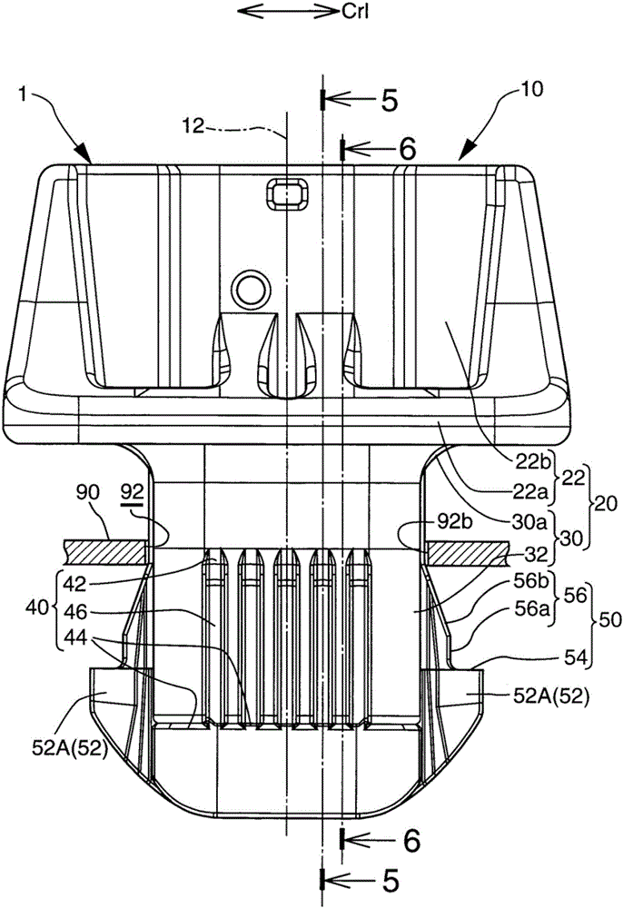
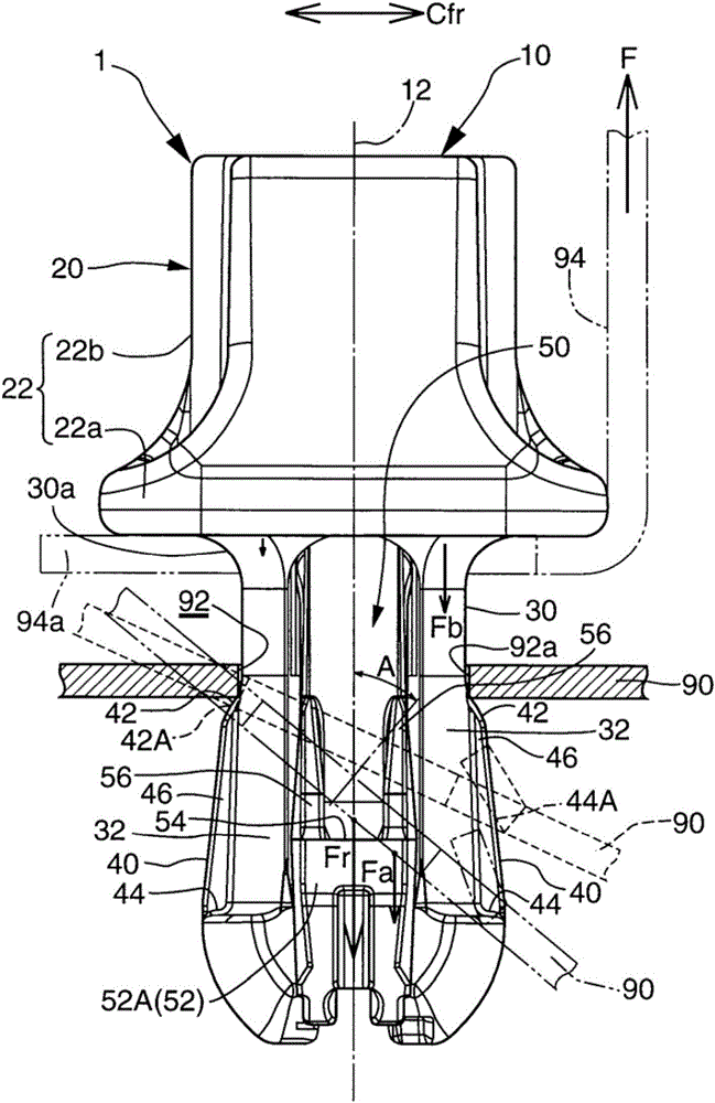
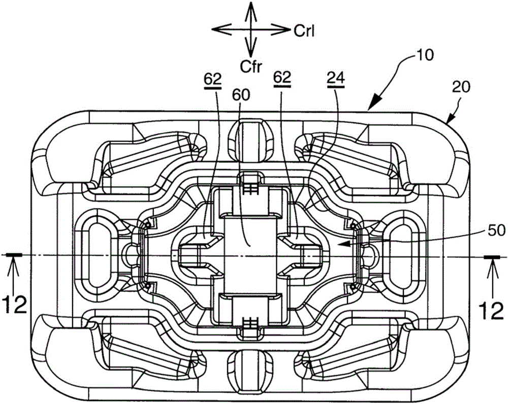
[0082] First, refer to Figure 1 to Figure 17 The fixing clip 10 according to the first embodiment and the fixing structure 1 for fixing the member 94 to be installed using the fixing clip 10 and their effects and technical advantages are explained together.
[0083] As in figure 1 with figure 2 As shown in the middle figure, the fixing clip 10 is used to fix the member 94 to be installed to the body panel 90 of the vehicle. The member 94 to be installed is, for example, a curtain airbag that can be called CSA (Curtain Shield Airbag). The member to be mounted 94 extends along the longitudinal direction of the rectangular clip fixing hole 92. The CSA expands and unfolds during a side collision or rollover of the vehicle, thereby protecting the head of the driver or passenger. When the member to be installed 94 is expanded and deployed, the pull-out load F is applied to the fixing clip 10 from the protrusion 94 a of the member to be installed 94. The body panel 90 is a panel of...
no. 2 example
[0146] The structure and technical effects of the first embodiment that can be commonly applied to the second embodiment also apply to the second embodiment.
[0147] In addition to the above structural and technical advantages, the fixing clip 10 and the fixing structure 1 for fixing the component to be installed according to the second embodiment further include the following structural and technical advantages:
[0148] As in Figure 18 with Figure 19 As shown in the middle figure, in the second embodiment, the lock pin 50 includes a load receiving surface 52B as a load receiving portion 52. The load receiving surface 52B is formed at the outer surface of the lock pin 50 located along the front-rear direction Cfr of the fixing clip 10. The load receiving surface 52B includes a surface that is inclined in a direction toward the end of the leg 30 and away from the central axis 12 of the fixing clip in a state where the lock pin 50 has been inserted into the bushing 20. More spec...
no. 3 example
[0157] The structure and technical effects of the first embodiment that are commonly applicable to the third embodiment also apply to the third embodiment.
[0158] In addition to the above structural and technical advantages, the fixing clip 10 and the fixing structure 1 for fixing the component to be installed according to the third embodiment further include the following structural and technical advantages:
[0159] As in Picture 20 As shown in the middle figure, in the third embodiment, the lock pin 50 includes a load receiving surface 52C as a load receiving portion 52. The load receiving surface 52C is formed at the outer surface of the lock pin 50 positioned in the front-rear direction Cfr of the fixing clip. The load receiving surface 52C includes a surface that is inclined in a direction toward the end of the leg 30 and away from the central axis 12 of the fixing clip in a state where the lock pin 50 has been inserted into the bushing 20.
[0160] On the other hand, the b...
PUM
 Abstract
Description
Claims
Application Information
 - R&D
- Intellectual Property
- Life Sciences
- Materials
- Tech Scout
- Unparalleled Data Quality
- Higher Quality Content
- 60% Fewer Hallucinations
Browse by: Latest US Patents, China's latest patents, Technical Efficacy Thesaurus, Application Domain, Technology Topic, Popular Technical Reports.
© 2025 PatSnap. All rights reserved.Legal|Privacy policy|Modern Slavery Act Transparency Statement|Sitemap|About US| Contact US: help@patsnap.com