Supercharge Your Innovation With Domain-Expert AI Agents!

Motor-driven steering lock device

A motor-driven, locking device technology, used in transportation and packaging, vehicle accessories for anti-theft, vehicle parts, etc., can solve the problems of small thread pitch and more time for pulling out operations.

Active Publication Date: 2005-12-14
U SHIN LTD
View PDF4 Cites 8 Cited by
  • Summary
  • Abstract
  • Description
  • Claims
  • Application Information

AI Technical Summary

Problems solved by technology

However, this device has a problem, also the extraction operation takes more time, this is due to the small thread pitch

Method used


Image

  • Motor-driven steering lock device
  • Motor-driven steering lock device
  • Motor-driven steering lock device

Examples


Embodiment Construction

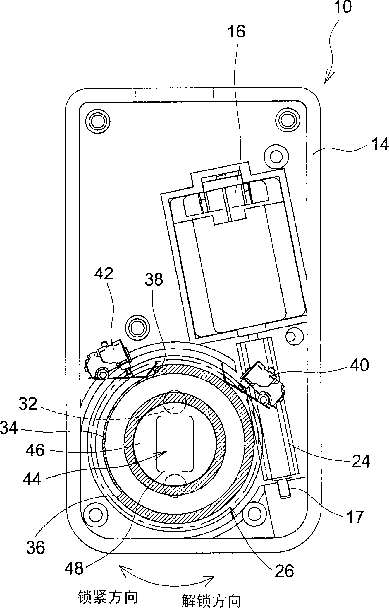
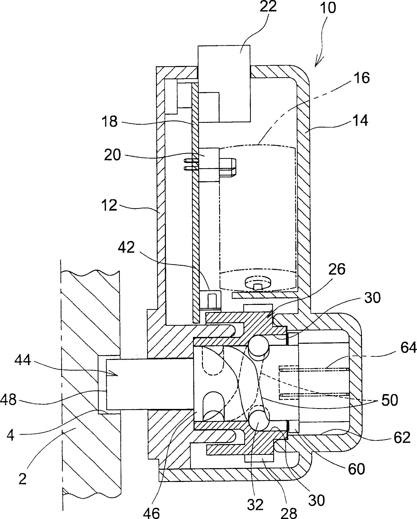
[0031] figure 1 is a plan view of a motor-driven steering lock device 10 according to an embodiment of the present invention, figure 2 It is a side sectional view of the motor-driven steering locking device 10 in a locked state. exist figure 2 in (also for Figure 4 and Figure 5 ), and for convenience, the left side is referred to as "front" and the right side is referred to as "rear".

[0032] The motor-driven steering lock 10 has a housing 14 which is closed with a cover 12 . Motor 16 is fixed in shell 14 li. The motor 16 is electrically connected to terminals 20 fixed on the printed board 18, and a controller unit (not shown) supplies power to the motor 16 from a connector 22 protruding on the side surface of the housing 14 through the printed board 19 and the terminals 20 , to make the motor 16 run forward or reverse. On the rotary shaft 17 of the motor 16 is mounted a worm 24 .

[0033]A cylindrical rotating body 26 is provided in the housing 14 . The rotating...


PUM


Abstract

In the motor-driven steering lock device 10 , cam grooves 50 inclined relative to a circumferential direction of a cylindrical part 46 of a lock bolt 44 are formed on an outer circumferential surface of the cylindrical part 46 , a cylindrical rotator 26 that is driven to rotate by an electric motor 16 is provided, the cylindrical part 46 of the lock bolt 44 is disposed inside the rotator 26 so as to be movable in an axial direction of the rotator 26 , and cam followers 32 held in longitudinal grooves 30 of the rotator 26 are moved in the cam grooves 50 so as to move the lock bolt 44.

Description

technical field [0001] This application is based on Japanese Patent Application No. 2004-167425 and No. 2004-167427, the contents of which are incorporated by reference. Background technique [0002] The invention relates to a motor-driven steering locking device, which is used for locking the steering wheel of automobiles or similar vehicles. [0003] Conventionally, steering locking devices for anti-theft purposes are known for locking the steering wheel of a motor vehicle or the like. Generally, in the steering lock device, there are engagement grooves on the outer circumference of the steering shaft that rotates with the operation of the steering wheel. When the deadbolt enters the groove and engages with the engagement groove, the rotation of the steering shaft is restricted and the steering wheel is locked. On the other hand, when the deadbolt leaves and disengages from the engagement groove, the steering shaft can rotate and the steering wheel is unlocked. [0004]...

Claims


Application Information

Patent Timeline
Patent Type & Authority Applications(China)
IPC IPC(8): B60R25/02
Inventor 福岛启介
Owner U SHIN LTD
Features
  • R&D
  • Intellectual Property
  • Life Sciences
  • Materials
  • Tech Scout
  • Unparalleled Data Quality
  • Higher Quality Content
  • 60% Fewer Hallucinations
Learn More