
Locks with Strong Latch Compression Springs

A technology of locks and compression springs, applied in the field of locks, can solve problems such as overcoming spring force movement and damage, and achieve a compact structure

Active Publication Date: 2019-12-03
ELDOMAT INNOVATIVE SICHERHEIT GMBH
View PDF2 Cites 0 Cited by
  • Summary
  • Abstract
  • Description
  • Claims
  • Application Information

AI Technical Summary

Problems solved by technology

The force required for the biasing of the latch spring is too great in that the component bearing the corresponding spring force cannot move against the spring force by an audible "hit" on the door, but other components , such as door frames, can also be damaged

Method used


Image

  • Locks with Strong Latch Compression Springs
  • Locks with Strong Latch Compression Springs
  • Locks with Strong Latch Compression Springs

Examples


Embodiment Construction

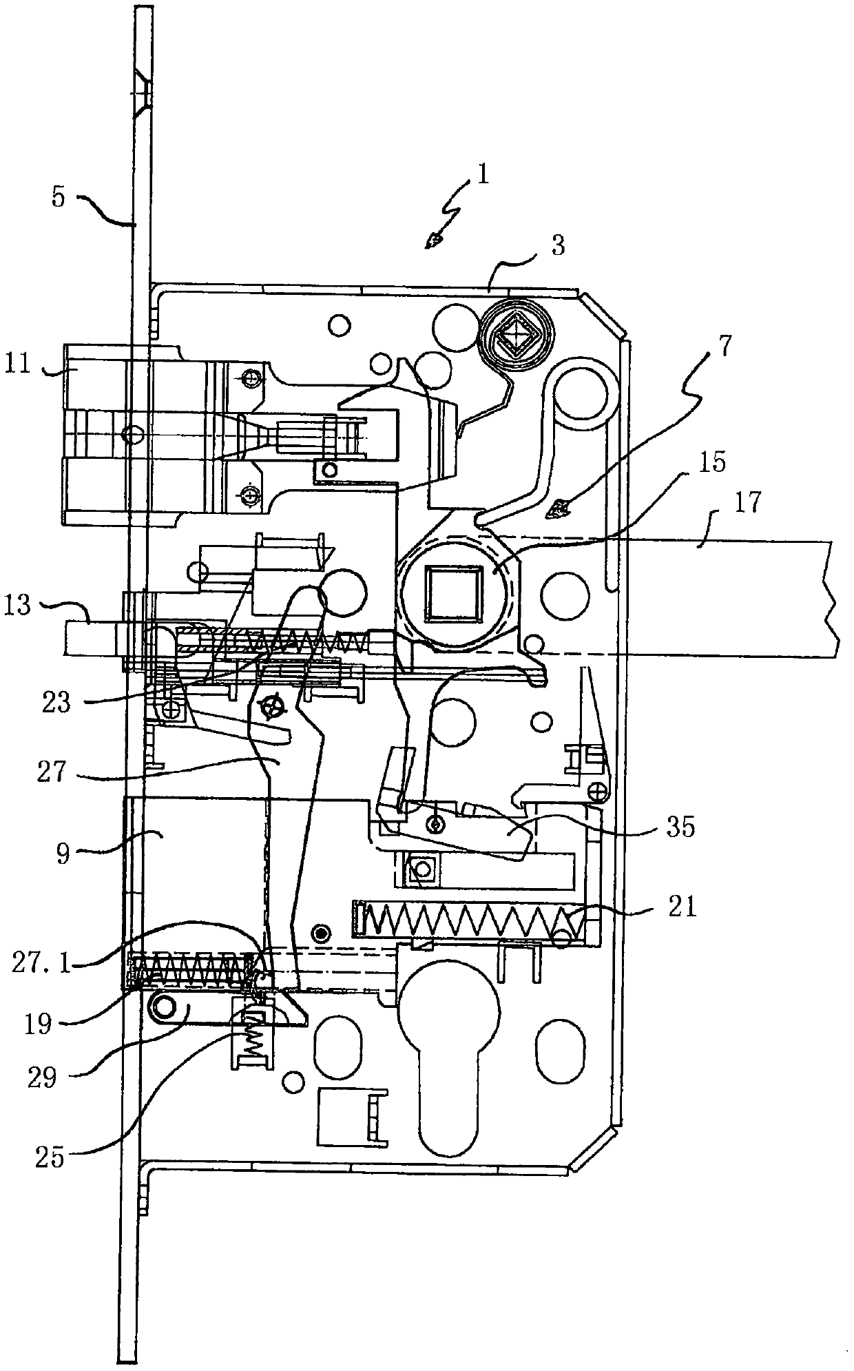
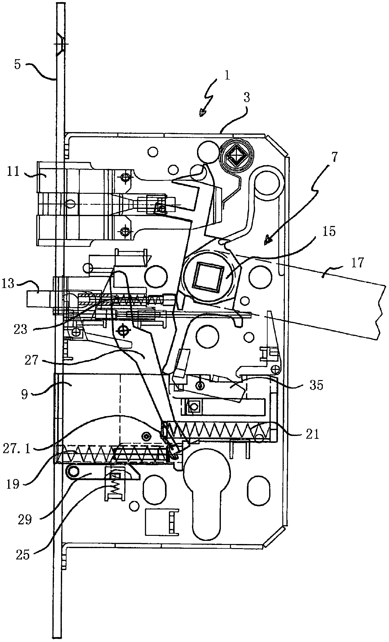
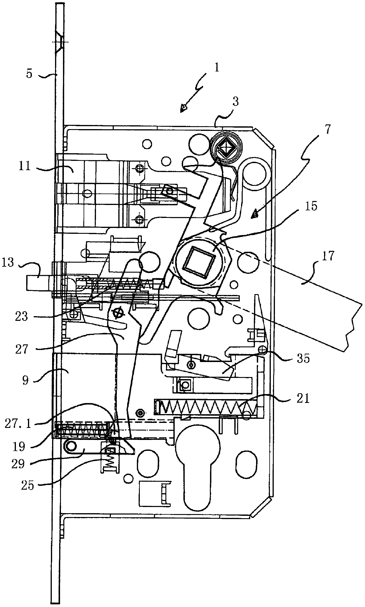
[0041] figure 1 A first embodiment of the lock 1 is shown schematically in a side view. The lock 1 includes a lock box 3 and a sealing panel 5 . A lock-unlock mechanism 7 is arranged in the lock box 3 . In this embodiment, the locking-unlocking mechanism 7 comprises in particular a latch part 9 , a bolt 11 , a trigger piece 13 and a head (Nuss) 15 on which a push rod 17 acts. The head 15 is structurally connected with the latch member 9 and the deadbolt 11 through various lever-shaped members, so that the operation of the push rod 17, that is, the clockwise rotation of the push rod 17 causes the deadbolt 11 to retract into the lock box 3 . Because deadbolt 11 is biased, so this deadbolt is in the unlocked state of lockset as follows: figure 1 location shown.

[0042] The lock-unlock mechanism 7 basically comprises four biasing elements. The first biasing element is the latch pressure spring 19 , the second biasing element is the return spring 21 , the third biasing eleme...


PUM


Abstract

The invention relates to a lock (1) with a powerful latch spring, the lock having a push rod (17) and a locking-unlocking mechanism (7) comprising at least one latch part (9), wherein the at least one The latch member (9) can move from the unlocked position to the locked position by means of the latch compression spring (19), which is characterized in that the latch compression spring (19) has a first Biased to support the locking movement of at least one latch member (9) in the unlocked position.

Description

technical field [0001] The invention relates to a lock with a push rod and a locking-unlocking mechanism comprising at least one latch part, wherein the at least one latch part can be moved from an unlocked position into a locked position by means of a latch compression spring. Background technique [0002] Such locks are well known in the art. It is especially used in combination with keyless locking systems where, for example, when the door is "slammed" or when the door leaf is oriented with its sealing panel opposite the striker plate in the door frame when the push rod or knob is actuated, Automatically trigger the locking process. During this orientation, this triggering generally depends on the spring force that needs to be overcome in order to bias the latch sufficiently to prevent it from unlocking. The biasing of the latch part is generally achieved by means of a latch compression spring. [0003] This prior art lockset is also used with only one bolt and with mu...

Claims


Application Information

Patent Timeline
Patent Type & Authority Patents(China)
IPC IPC(8): E05B15/04E05B15/10E05B63/14E05B63/08E05B63/20
CPCE05B15/04E05B15/101E05B63/08E05B63/146E05B63/20E05B2063/207E05B59/00E05B2001/0076E05C9/02E05B2015/0448E05B7/00E05F1/08E05F3/221E05Y2201/474E05C1/12
Inventor E·巴尔托迪
Owner ELDOMAT INNOVATIVE SICHERHEIT GMBH
Learn More