Rubber sleeve without copper sheet coating inner side face of sealing ring at lower end, packer and bridge plug

A sealing ring and inner surface technology, which is applied in the field of packers and bridge plugs, and the inner surface of the lower end sealing ring is not coated with copper skin. It can solve the problems of rubber casing splitting, sealing failure, and rubber casing loss of elasticity. To achieve the effect of preventing the rubber tube from splitting, preventing failure, and increasing the range of compressive strength

Inactive Publication Date: 2016-10-12
TIANDING SEALING TECH BEIJING CO LTD
View PDF0 Cites 1 Cited by
  • Summary
  • Abstract
  • Description
  • Claims
  • Application Information

AI Technical Summary

Problems solved by technology

According to the inventor's test, when the first axial pressure is 30MPa, the inventor finds that almost all of the rubber cartridges will have a shoulder, and when the second axial pressure (such as 15Ma) is further applied, all the rubber cartridges will be at the same time. Cleave at the shoulder leading to seal failure
[0008]Furthermore, the inventor also found that even if the rubber cartridge can be sealed, when bottomhole gas and other substances impact the rubber cartridge, the high-temperature and high-pressure steam contained therein will be less Molecules will degrade the rubber cartridge of polymer materials, causing the rubber cartridge to lose its elasticity at the lower end first and unable to play a sealing role, affecting the long-term sealing of the rubber cartridge

Method used


Image

  • Rubber sleeve without copper sheet coating inner side face of sealing ring at lower end, packer and bridge plug
  • Rubber sleeve without copper sheet coating inner side face of sealing ring at lower end, packer and bridge plug
  • Rubber sleeve without copper sheet coating inner side face of sealing ring at lower end, packer and bridge plug

Examples


Embodiment Construction

[0064] The directions "up" and "down" described below are based on figure 2 described as a reference.

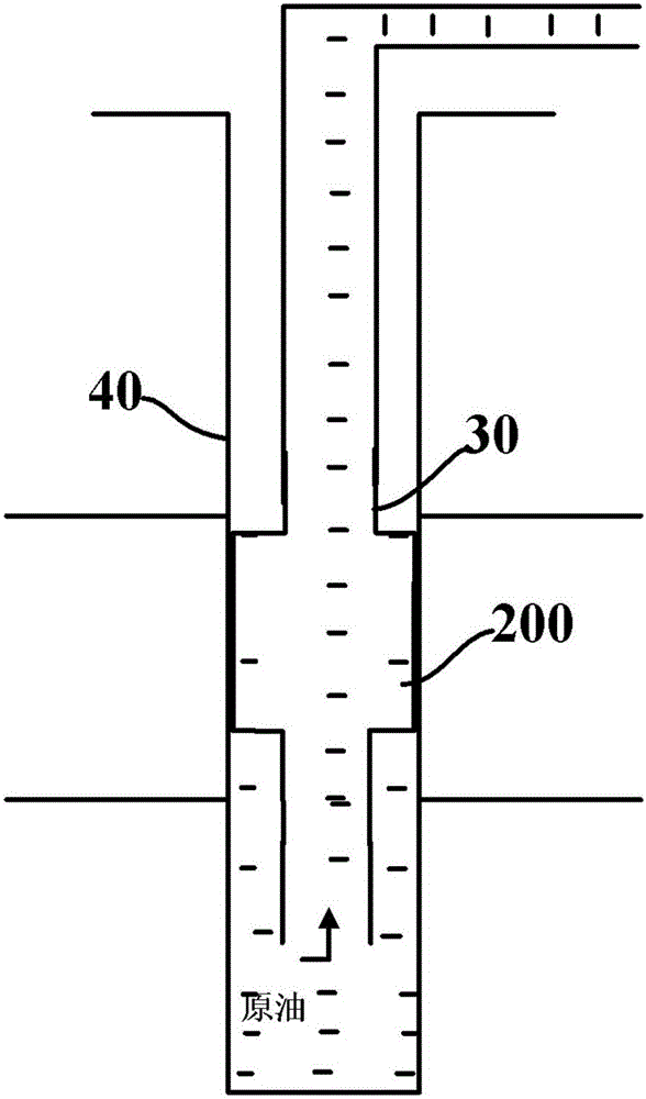
[0065] like figure 1 The compression packer 200 is shown with the cartridge 10 of the present application. The compression packer 200 is connected to the base pipe 30 and placed in the casing 40 . The compression packer 200 needs to separate different oil layers and water layers in the wellbore and withstand a certain pressure difference. Get out smoothly.

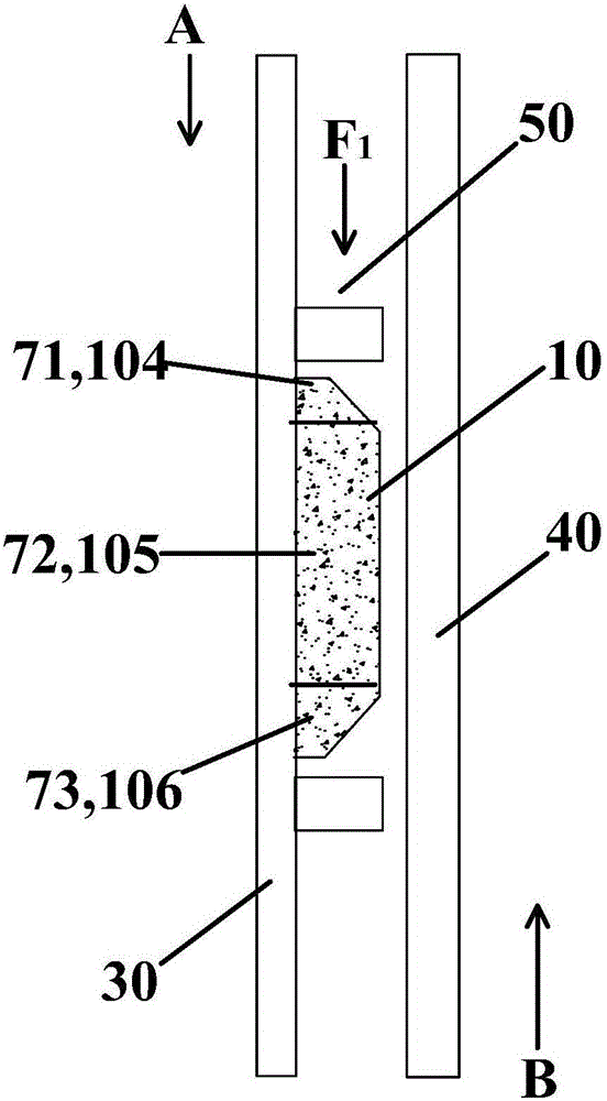
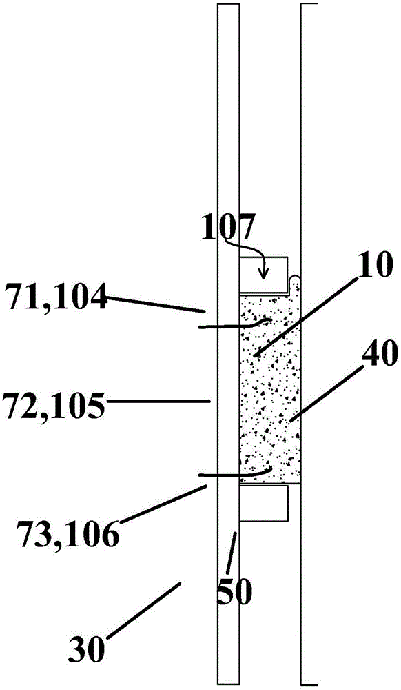
[0066] like figure 2 As shown, the rubber cartridge 10 is located in the annular space formed by the sleeve 40 and the central tube 30, and the rigid spacer ring 50 provides the first axial pressure F from top to bottom (ie, the first axial direction A) in the axial direction. 1 , in other embodiments, the rigid spacer ring 50 can also be removed and the first axial pressure F can be applied to the rubber cartridge 10 1 other components instead. like figure 2 As shown, the two ends of the rubber cartridge 10 a...


PUM


Abstract

The invention relates to the field of sealing, in particular to a rubber sleeve which is used in the oil exploitation industry, can bear high temperature and high pressure and does not coat the inner side face of a sealing ring at the lower end with a copper sheet, a packer and a bridge plug. The outside of the sealing ring at the lower end of the rubber sleeve is coated with a first copper sheet; the upper surface, the lower surface and the outer side face of the sealing ring at the lower end are coated with the first copper sheets but the inner side face of the sealing ring at the lower end is not coated with the first copper sheet; the thicknesses of the first copper sheets are set as follows: when an upper end part bears a first axial pressure, the sealing ring at the lower end deforms in the radial direction, further the first copper sheet distributed on the inner side face of the sealing ring at the lower end is enabled to prop against a central pipe, and the first copper sheet distributed on the outer surface of the sealing ring at the lower end is enabled to prop against a casing pipe. The sealing ring at the lower end, disclosed by the invention, is coated with the first copper sheets, so that a degradation effect of micromolecules of high-temperature and high-pressure steam on the rubber sleeve is reduced or prevented, and the long-term efficacy of rubber sleeve sealing is improved.

Description

technical field [0001] The present application relates to the field of sealing, in particular to a rubber sleeve, a packer and a bridge plug which are used in the oil exploitation industry and can withstand high temperature and high pressure, and the inner surface of the lower sealing ring is not coated with copper skin. Background technique [0002] Packer is a key tool for downhole oil production in oilfields. It is widely used in various operations such as oilfield injection, layered reconstruction, layered oil production, mechanical pipeline water plugging, etc. The packer needs to isolate the annular space to achieve Oil and gas stratification, and the core component to achieve annular isolation is the rubber cartridge. Bridge plug is also a tool for oil and gas stratification commonly used in oil production. The main difference between the packer and the bridge plug is that the packer is generally temporarily left in the well during the construction of fracturing, aci...

Claims


Application Information

Patent Timeline
IPC IPC(8): E21B33/128E21B33/134
CPCE21B33/1208E21B33/1277E21B33/128E21B33/134
Inventor 宋炜隆学武贾晓红
Owner TIANDING SEALING TECH BEIJING CO LTD
Why Eureka
Try Eureka