Observation system and method for aerodynamic force test and flapping wing flow field of flapping-wing micro air vehicle

A technology of a flapping aircraft and an observation system, which is applied in the aerospace field, can solve the problems of less experimental equipment for a micro flapping aircraft, restricting the research and development of the flapping aircraft, and less experimental data for the flapping aircraft, etc. High practical performance and comprehensive data effect

Inactive Publication Date: 2016-10-12
SHANGHAI UNIV OF ENG SCI
View PDF9 Cites 24 Cited by
  • Summary
  • Abstract
  • Description
  • Claims
  • Application Information

AI Technical Summary

Problems solved by technology

At present, the existing experimental equipment is mainly used for the experimental research of conventional aircraft, and the experimental equipment for miniature flapping-wing aircraft is less and imperfect, and there are relatively few relevant experimental data of flapping-wing aircraft for reference, which limit

Method used


Image

  • Observation system and method for aerodynamic force test and flapping wing flow field of flapping-wing micro air vehicle
  • Observation system and method for aerodynamic force test and flapping wing flow field of flapping-wing micro air vehicle
  • Observation system and method for aerodynamic force test and flapping wing flow field of flapping-wing micro air vehicle

Examples


Embodiment Construction

[0038] The present invention will be described in detail below in conjunction with the accompanying drawings and specific embodiments. This embodiment is carried out on the premise of the technical solution of the present invention, and detailed implementation and specific operation process are given, but the protection scope of the present invention is not limited to the following embodiments.

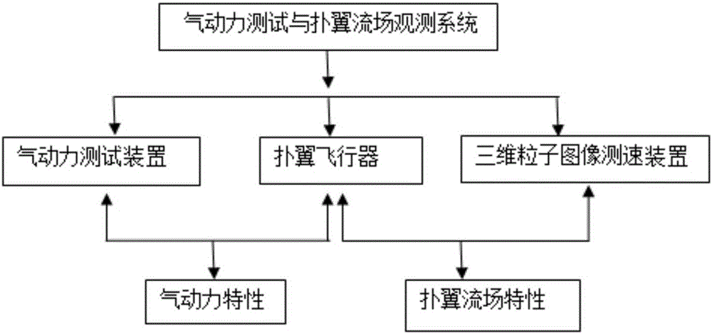
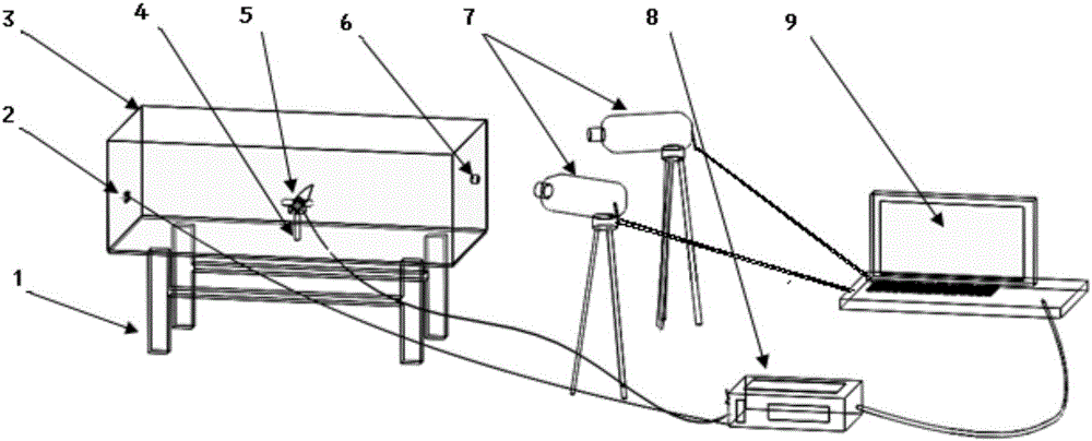
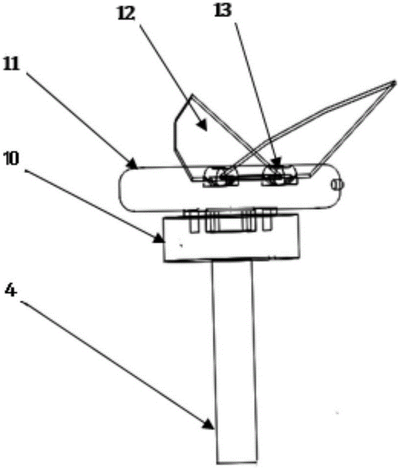
[0039] Such as Figure 1 ~ Figure 3 As shown, the present invention provides a micro flapping-wing aircraft aerodynamic testing and flapping-wing flow field observation system, which mainly includes: flapping-wing aircraft 5, aerodynamic testing device, and three-dimensional particle image velocimetry device. The aerodynamic test device mainly includes a six-dimensional force sensor 10, an angle sensor 13, a diffuse reflection switch 2, a data collector 8, and a host computer 9. The three-dimensional particle image velocity measurement device mainly includes: tracer particles, laser ...


PUM


Abstract

The invention relates to an observation system and method for an aerodynamic force test and a flapping wing flow field of a flapping-wing micro air vehicle. The system comprises an observation box, a flapping-wing micro air vehicle, an aerodynamic force testing device, a three-dimensional particle image velocity measuring device, and an upper computer. The observation box is used for accommodating an observation object and an observation device. The flapping-wing micro air vehicle is used as an observation object for observation. The aerodynamic force testing device is used for recording various parameters of aerodynamic force characteristics of the flapping-wing micro air vehicle during the flapping process. The three-dimensional particle image velocity measuring device is used for recording various parameters of flapping-wing flow field characteristics of the flapping-wing micro air vehicle during the flapping process. The upper computer is used for displaying a lifting resistance parameter, a flapping frequency parameter, and a flow field characteristic analysis chart of the flapping-wing micro air vehicle. The method includes a step of carrying out aerodynamic force characteristic observation by using a aerodynamic force testing device and a step of carrying out flapping wing flow field characteristic observation by using the three-dimensional particle image velocity measuring device. Compared with the prior art, the system and method have advantages of complete equipment, excellent special performance and great simpleness and convenience.

Description

technical field [0001] The invention relates to the field of aerospace, in particular to a system and method for aerodynamic testing and flapping-wing flow field observation of a miniature flapping-wing aircraft. Background technique [0002] The wings of birds and insects have strong maneuverability, can take off at any time and fly vertically, can also perform rapid flight turns, and can hover continuously. The super flying ability of these flying creatures has gradually attracted human beings. of great concern. Micro-flapping-wing aircraft is a kind of bionic aircraft. It is a new concept aircraft based on bionics. It mainly generates lift and thrust to maintain flight by simulating the action of flapping wings of flying creatures. Compared with traditional fixed-wing and rotary-wing micro-aircraft, the micro-flapping-wing aircraft only needs to rely on periodic flapping movements to generate lift to maintain flight, and has better maneuverability and flexibility. Due t...

Claims


Application Information

Patent Timeline
IPC IPC(8): G01M9/00G01M9/06
CPCG01M9/00G01M9/06
Inventor 田培培金晓怡邢亚飞
Owner SHANGHAI UNIV OF ENG SCI
Why Eureka
Try Eureka