Power supply device

A technology of power supply equipment and power supply unit, which is applied in the direction of data processing power supply, measuring device, measuring flow rate/mass flow rate, etc. It can solve the problems of inability to move relative to each other, connectors are easy to fall off, and connection is inconvenient, so as to avoid open circuit and avoid Plug-in line short circuit, easy to adjust the effect

Inactive Publication Date: 2016-10-12
STATE GRID SHANDONG ELECTRIC POWER CO LONGKOU POWER SUPPLY CO
View PDF4 Cites 7 Cited by
  • Summary
  • Abstract
  • Description
  • Claims
  • Application Information

AI Technical Summary

Problems solved by technology

Due to the plug-in method, when vibration occurs, the connectors are easy to fall off, resulting in easy interruption of power supply, and during the installation process, usually after a power supply unit is installed, it cannot be moved relative to each other, resulting in inconvenient connection

Method used


Image

  • Power supply device
  • Power supply device

Examples


Embodiment 1

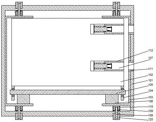
[0023] Such as figure 1 , 2 As shown, a power supply device includes a rectangular parallelepiped cover 101 and a power supply unit 102 arranged inside the cover 101, and brackets 103 are respectively provided on two opposite side walls inside the cover 101 The middle part of the bracket 103 is attached to the inner wall of the cover 101, both ends of the bracket 103 are bent inward to form a U-shaped structure, and the power supply unit 102 is clamped to the two Inside the U-shaped structure of the bracket 103, baffles 104 are provided on the lower ends of both sides of the power supply unit 102, and a rotating shaft 105 is provided between the baffles 104, and the two ends of the rotating shaft 105 are respectively rotatably connected On the baffle 104, a support bar 106 is provided on the inner side of the bracket 103, and the rotating shaft 105 is attached to the support bar 106 to roll relative to each other. On the side wall of the cover 101 The power supply unit 102 is p...

Embodiment 2

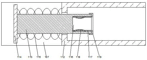
[0026] In this embodiment, on the basis of embodiment 1, in order to prevent the insertion depth of the joint from being unable to be controlled when the line is inserted, in this embodiment, preferably, a through hole is provided at the bottom of the metal connecting pipe 112, and A reset rod 113 is inserted into the through hole, a circular plate 114 is provided at one end of the reset rod 113 extending out of the through hole, and a reset spring 115 is sleeved on the outside of the reset rod 113. One end of the return spring 115 is attached to the end surface of the circular plate 114 facing the metal connecting tube 112, and the other end of the return spring 115 is attached to the metal connecting tube 112 facing the circular plate. The end face of the plate 114 on one side. When the connector is inserted inside the metal connecting tube, the connector and the metal connecting tube are connected to each other, so that the end of the connector is attached to the reset rod. ...

Embodiment 3

[0031] In this embodiment, in order to facilitate the installation of the positioning rod, preferably, a threaded hole is provided on the cover 101, an external thread is provided on the outer wall of the positioning rod 108, and the positioning rod 108 is threadedly connected On the cover 101. After installing the bracket on the inside of the cover, screw the positioning rod on the cover, insert the lower end of the positioning rod into the positioning tube on the bracket, and make the lower end of the positioning rod hang relative to the positioning tube. Due to the threaded connection, the depth of the positioning rod inserted into the positioning tube can be determined as required.

[0032] Further preferably, in this embodiment, in order to fix the positioning rod, preferably, one end of the positioning rod 108 penetrates the outside of the cover body 101, and the positioning rod 108 extends out of the cover body 101 A fixed sleeve 120 is provided on one side, and the fixed...


PUM


Abstract

The invention discloses a power supply device. The power supply device comprises a cuboid cover and a power supply unit arranged on the inner sides of the cover, supports are arranged on the two opposite inner side walls of the cover respectively, the middles of the supports are attached to the inner walls of the cover, the two ends of the supports are bent inwards to form U-shaped structures, and the power supply unit is clamped on the inner sides of the U-shaped structures of the two supports; baffles are arranged on the lower end faces of the two sides of the power supply unit, a rotating shaft is arranged between the baffles, the two ends of the rotating shaft are rotationally connected to the baffles respectively, supporting strips are arranged on the inner sides of the supports, and the rotating shaft is attached to the supporting strips and relatively rotates. According to the power supply device, as the cover structure is adopted, the power supply unit is centrally installed on the inner sides of the cover, and a power source can be conveniently inserted and connected; meanwhile, as the supports provided with vibration-reducing mechanisms are adopted, the vibration resistance of the overall structure can be improved, and better stability can be achieved.

Description

[0001] technical field [0002] The invention relates to a power supply device. Background technique [0003] Existing power supply units used for equipment such as servers usually adopt a method of plugging power lines into power sources. Due to the plug-in mode, when vibration occurs, the plug-in parts are easy to fall off, causing the power supply to be easily interrupted. Moreover, during the installation process, usually after a power supply unit is installed, it cannot be relatively moved, resulting in inconvenient connection. Contents of the invention [0004] The purpose of the present invention is to provide a power supply device, which can improve the problems existing in the prior art. By adopting the cover body structure, the power supply unit is collectively installed inside the cover body, which can facilitate the plugging of the power supply. The support can improve the seismic performance of the overall structure and make it more stable. [0005] The pres...

Claims


Application Information

Patent Timeline
Patent Type & Authority Applications(China)
IPC IPC(8): G06F1/26
CPCG06F1/26
Inventor 吴志军韩军吕刚于兆军李凤邹丽娜
Owner STATE GRID SHANDONG ELECTRIC POWER CO LONGKOU POWER SUPPLY CO
Why Eureka
Try Eureka