360-degree full-angle wide-area scanning head

A scanning head and wide-area technology, which is applied in the field of 360-degree full-angle wide-area scanning head, can solve the problems that the accuracy and speed of the galvanometer cannot be improved, the quality of the galvanometer increases, and the scanning accuracy and speed cannot be improved, so as to improve the scanning accuracy And the effect of speed and weight reduction

Inactive Publication Date: 2018-10-12
曾林旺
View PDF6 Cites 0 Cited by
  • Summary
  • Abstract
  • Description
  • Claims
  • Application Information

AI Technical Summary

Problems solved by technology

[0002] The existing scanning head adopts the dual vibrating mirror method, that is, the vibrating mirror 1 rotates around the horizontal axis and the space disjoint vibrating mirror 2 rotates around the vertical axis. The superposition of the two vibrating mirrors realizes scanning within a certain area. The size of the scanning area is determined by The size of the lens is determined, and the zoom is realized by the field lens. To realize a wide range of scanning, the size of the vibrating mirror must be increased, that is, the quality of the vibrating mirror will increase, and the required space will increase. This will bring great inconvenience to the motor driving the vibrating mirror. Large burden, resulting in the inability to improve the accuracy and speed of the galvanometer movement, resulting in the inability to improve the scanning accuracy and speed, and it is difficult to expand the scanning range
At present, light scanning heads are widely used in optical application control occasions such as stage lights, laser marking, and printing, and these scenes often have great requirements for scanning range, and it is difficult for existing scanning heads to achieve full-angle wide-area scanning

Method used


Image

  • 360-degree full-angle wide-area scanning head
  • 360-degree full-angle wide-area scanning head
  • 360-degree full-angle wide-area scanning head

Examples


Embodiment Construction

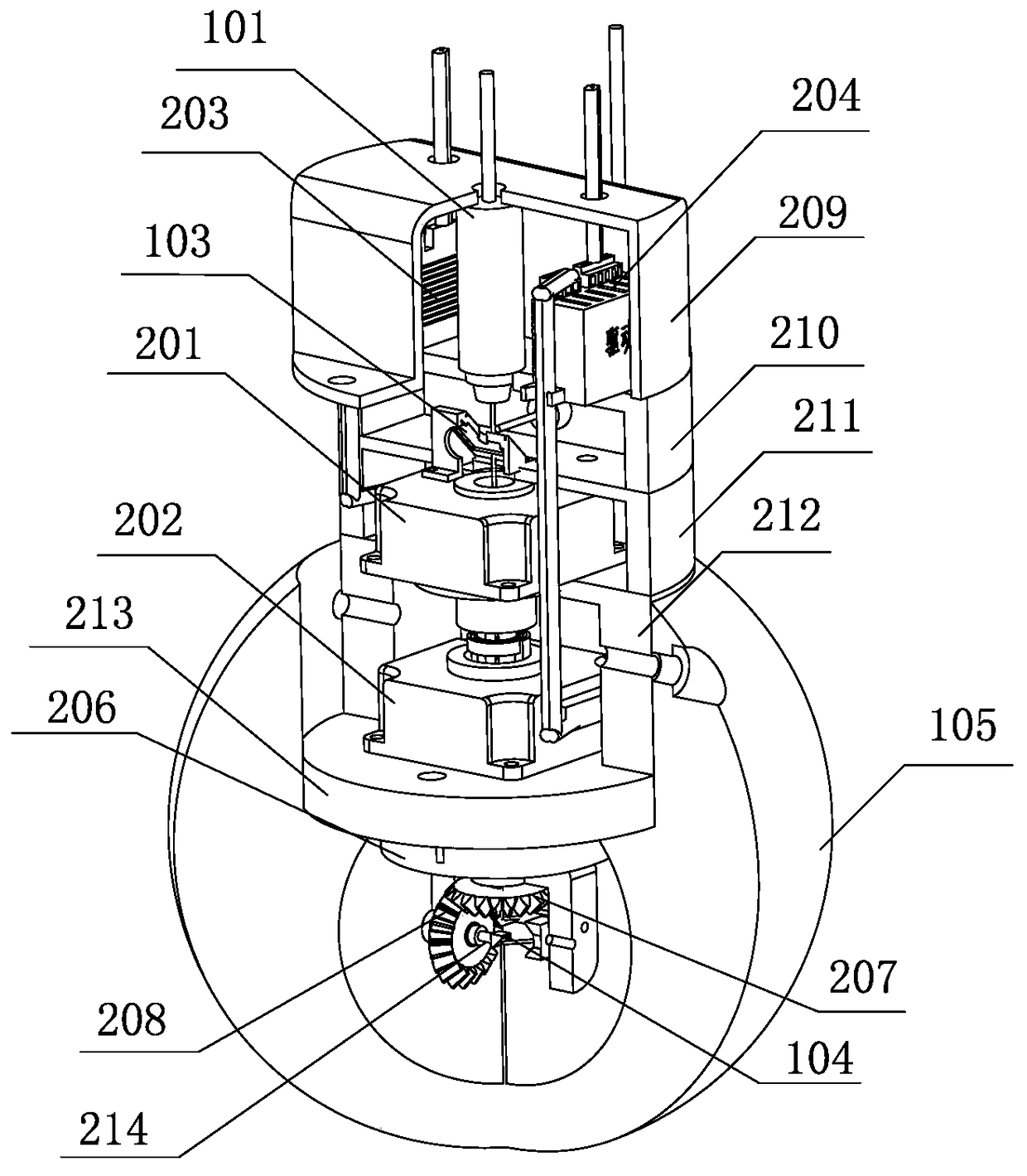
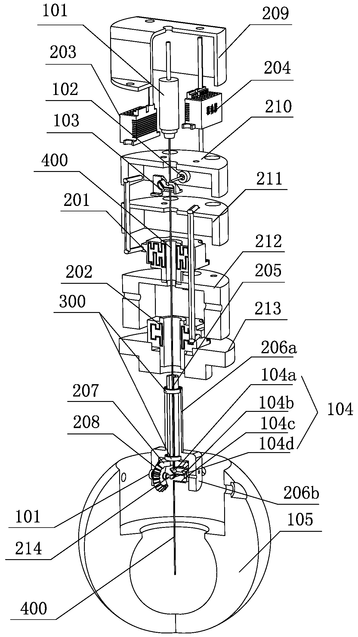
[0043] like Figures 1 to 7 As shown, the 360-degree full-angle wide-area scanning head disclosed in Embodiment 1 of the present invention is composed of a photoelectric component 100 and a driving component 200;

[0044] The photoelectric component 100 includes a vertical light source 101, a horizontal light source 102, a half mirror 103, a full mirror group 104 and a field mirror 105; Above the half-mirror 103, the horizontal light source 102 is arranged on the side of the half-mirror 103, and the full mirror group 104 is arranged on the half-mirror 103 below; the vertical light source 101 and the horizontal light source 102 are laser light sources;

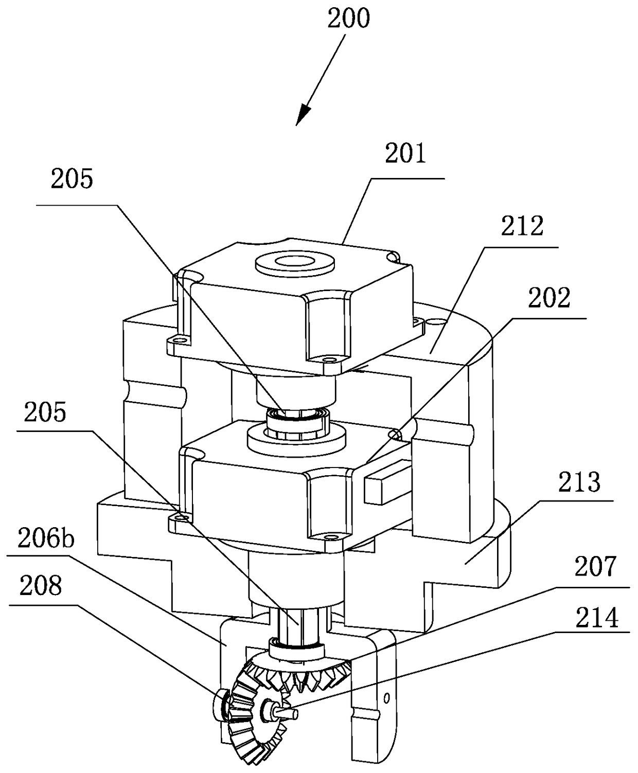
[0045] The drive assembly 200 includes a vertical drive motor 201, a horizontal drive motor 202, a first driver 203, a second driver 204, a vertical rotation shaft 205, a horizontal rotation bracket 206, a vertical rotation bevel gear 207 and a horizontal rotation bevel gear 208 ; The vertical drive motor 201, the horizontal d...


PUM


Abstract

The invention discloses a 360 degree full angle wide area scanning head consisting of a photoelectric assembly and a driving assembly. The photoelectric assembly comprises a vertical light source, a horizontal light source, a semi-transparent and semi-reflective mirror, a total reflective mirror group and a field lens. The driving assembly comprises a vertical driving electric motor, a horizontal driving electric motor, a first driver, a second driver, a vertical rotating shaft, a horizontal rotating support rack, a vertical rotating bevel gear and a horizontal rotating bevel gear. An upper end of the horizontal rotating support rack is provided with a horizontal rotation driving rod having a shaft hole, a lower end of the horizontal rotating support rack is a total reflective mirror group installation cover, a lower end of the vertical rotating shaft extends into the total reflective mirror group installation cover, the vertical rotating bevel gear is arranged in the total reflective mirror group installation cover in pivoted manner after being connected with the lower end of the vertical rotating shaft, the horizontal rotating bevel gear is arranged in the total reflective mirror group installation cover in a pivoted manner via a horizontal rotating shaft mounted on a side wall of the total reflective mirror group installation cover, the total reflective mirror group is fixed on the horizontal rotating shaft, and the vertical rotating shaft and the vertical rotating bevel gear are provided with central light holes. Via the 360 degree full angle wide area scanning head, lamp light scanning breadth, speed and precision can be increased.

Description

technical field [0001] The invention relates to the technical field of lighting scanning equipment, in particular to a 360-degree full-angle wide-area scanning head. Background technique [0002] The existing scanning head adopts the dual vibrating mirror method, that is, the vibrating mirror 1 rotates around the horizontal axis and the space disjoint vibrating mirror 2 rotates around the vertical axis. The superposition of the two vibrating mirrors realizes scanning within a certain area. The size of the scanning area is determined by The size of the lens is determined, and the zoom is realized by the field lens. To realize a wide range of scanning, the size of the vibrating mirror must be increased, that is, the quality of the vibrating mirror will increase, and the required space will increase. This will bring great inconvenience to the motor driving the vibrating mirror. The large burden leads to the inability to improve the accuracy and speed of the galvanometer movemen...

Claims


Application Information

Patent Timeline
Patent Type & Authority Patents(China)
IPC IPC(8): G06K7/10
CPCG06K7/10831
Inventor 曾林旺
Owner 曾林旺
Why Eureka
Try Eureka