An Optical Phased Array

An optical phased array and phased array technology, applied in the field of optical phased array, can solve the problems of increased grating lobe strength, grating lobe strength greater than main lobe strength, large grating lobe, etc., to overcome the large attenuation of the main lobe Effect

Active Publication Date: 2019-12-27
TSINGHUA UNIV
View PDF4 Cites 0 Cited by
  • Summary
  • Abstract
  • Description
  • Claims
  • Application Information

AI Technical Summary

Problems solved by technology

[0006] 1. The scanning angle is too small. Most of the reported optical phased array scanning angles are only about ±10°
[0007] 2. The requirements on the width and period of the waveguide are too strict, which leads to difficulties in the manufacturing process: if you want to achieve the scanning requirements in the direction of ±90° To minimize grating lobes, the duty cycle must be close to 1
[0008] 3. In terms of grating lobe strength, traditional optical phased array grating lobes are larger
[0009] 4. If figure 2 As shown, in the traditional phased array scanning process, as the scanning angle increases, the intensity of the main lobe gradually decreases, and the intensity of the grating lobe gradually increases, and even the phenomenon that the intensity of the grating lobe is greater than the intensity of the main lobe may appear, which is obviously what we do not want to see Arrived

Method used


Image

  • An Optical Phased Array
  • An Optical Phased Array
  • An Optical Phased Array

Examples


Embodiment 1

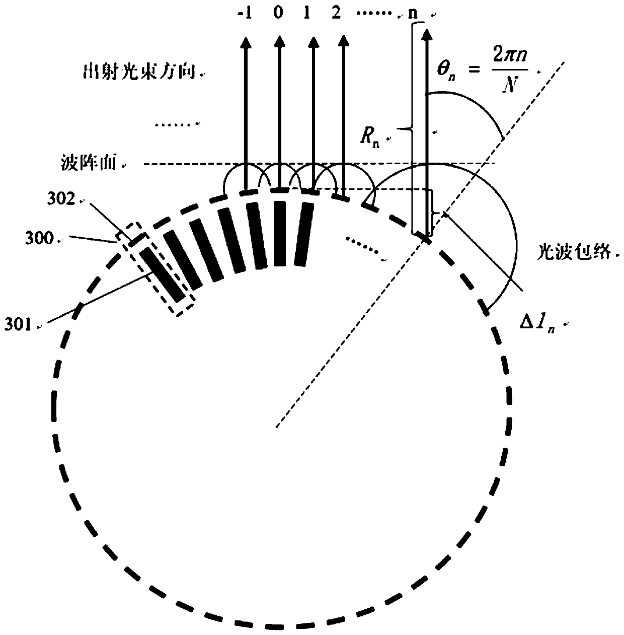
[0038] Figure 3a with Figure 3b It is a schematic structural diagram of a one-dimensional annular optical phased array according to an embodiment of the present invention. The annular phased array is made up of N phased array units, each phased array unit includes a phase modulator 301 for adjusting the additional phase of the phased array unit 300, and the N phase modulators are arranged on a plane Arranged in a circular shape, the waveguide transmitting unit 302 at one end of each phase modulator faces outside the center of the circular ring, and N is a natural number. Figure 3a is a schematic diagram of the case where the outgoing beam is not deflected, Figure 3b It is a schematic diagram of the case where the outgoing beam is deflected. Depend on Figure 3a with Figure 3b It can be seen that by adjusting the additional phases of different phase modulators and controlling the output phases of different phased array units, the optical phased array can achieve coher...

Embodiment 2

[0112] Accumulating the one-dimensional annular optical phased array in the first embodiment in the axial direction can obtain a spatially two-dimensional scanning optical phased array, whose scanning in the horizontal direction has been described above, and in the vertical direction The scanning is achieved by changing the phase difference of the corresponding units in adjacent layers. The scanning range of the three-dimensional and two-dimensional cylindrical optical phased array of the embodiment of the present invention is as follows: Figure 7 As shown, it can realize 360° large-scale scanning in the horizontal azimuth angle, but it is still limited by the inherent defects of the traditional optical phased array in the elevation angle.

[0113] Due to the unique scanning range of this optical phased array, it is very suitable for use in the scanning of vehicle-mounted lidar, and its detection range covers the surrounding area of ​​the self-driving vehicle ring.

[0114] ...

Embodiment 3

[0151] The cylindrical optical phased array can only realize 360° large-scale scanning in one direction. If you want to realize 360° scanning in two directions at the same time, you need to superimpose several layers of circular optical phased arrays into an approximately spherical array. The number of phased array units contained in the one-dimensional circular optical phased array on the plane decreases from the center of the circle along the two directions of the axial direction, forming a spherical phased array in which the array elements are not evenly arranged. The arrangement of the grating lobes is also greatly compressed. The theoretical analysis of the spherical optical phased array is still analyzed according to the diffraction superposition model. The schematic diagram of the spherical phased array structure is as follows: Figure 9 shown. The short line in the figure is the phased array transmitting unit.


PUM


Abstract

The invention discloses an optical phased array. The optical phased array is composed of N phased array units, each phased array unit comprises a phase modulator for adjusting the additional phase ofthe phased array unit, N phase modulators are arranged in a circular shape on a plane, a waveguide transmitting unit at one end of each phase modulator faces the outer side of a circular center, and Nis a natural number; the working range of the phased array units is shown in the description, n is an integer, the phase modulator of the nth phased array unit adjusts the additional phase as shown in the description according to the change of the exit angle omega, d is the spacing of the adjacent waveguide transmitting units, and lambada is the wavelength of a light source. By adopting the optical phased array, wide-range 360-degree equal amplitude scanning is achieved. The optical phased array achieves multi-point scanning.

Description

technical field [0001] The invention relates to the technical field of optical phased arrays, in particular to an optical phased array. Background technique [0002] Optical phased array technology (OPA—Optical Phased Array), which has become a research hotspot in recent years and has developed rapidly, is a new electronically controlled beam scanning technology, and its working principle is similar to that of microwave phased array. Its core components are composed of several phase modulation units. By controlling the applied voltage of the phase modulator, the additional refractive index inside the modulator can be controlled, so that the additional phase of the light field at the output end of each phase modulator can be controlled, so that the deflection of the propagation direction of the radiation beam can be realized. Optical phased array technology is a high-resolution, high-precision, and fast beam control technology with broad application prospects, so it has beco...

Claims


Application Information

Patent Timeline
Patent Type & Authority Patents(China)
IPC IPC(8): G02F1/29
CPCG02F1/292
Inventor 熊兵刘学成罗毅孙长征郝智彪
Owner TSINGHUA UNIV
Why Eureka
Try Eureka