Antenna device and terminal device

An antenna device and curved section technology, which is applied in the field of antenna devices and terminal equipment, can solve problems such as the adverse effects of the radiation performance of the slot antenna in the housing, and achieve the effect of ensuring integrity and avoiding radiation performance

Active Publication Date: 2016-10-12
GUANGDONG OPPO MOBILE TELECOMM CORP LTD
View PDF5 Cites 8 Cited by
  • Summary
  • Abstract
  • Description
  • Claims
  • Application Information

AI Technical Summary

Problems solved by technology

[0003] However, when the user holds the terminal device, the user's hand usually comes into contact with the micro-slit strip. Since the human body can be considered as a conductor, it will adversely affect the radiation performance of the slot antenna of the housing.

Method used


Image

  • Antenna device and terminal device
  • Antenna device and terminal device
  • Antenna device and terminal device

Examples


Embodiment 1

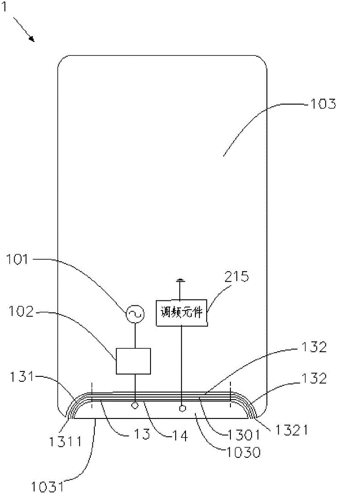
[0026] refer to figure 1 , shows the antenna device 1 according to the first embodiment of the present invention, the antenna device 1 includes a radio frequency transceiver circuit 101, a matching circuit 102, a housing 103 and a frequency modulation element 104, wherein the radio frequency transceiver circuit 101 communicates with the radio frequency transceiver circuit 102 through the matching circuit 102 The housing 103 is electrically connected, the radio frequency transceiver circuit 101 is used as a feed source of the antenna device 1, and the matching circuit 102 is used for performing impedance matching and balance matching between the radio frequency transceiver circuit 101 and the housing 103, so as to ensure the efficiency of the antenna device 1, Both the radio frequency transceiver circuit 101 and the matching circuit 102 belong to conventional means in the prior art, and will not be described in detail here.

[0027] The casing 103 is an all-metal casing, which ...

Embodiment 2

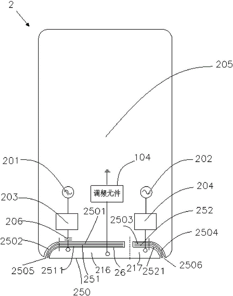
[0035] refer to figure 2, shows the antenna device 2 according to the second embodiment of the present invention, the antenna device 2 includes a first radio frequency transceiver circuit 201, a second radio frequency transceiver circuit 202, a first matching circuit 203, a second matching circuit 204, a housing 205 and FM element 215. Wherein, the first radio frequency transceiver circuit 201 is electrically connected to the housing 205 through the first matching circuit 202, the second radio frequency transceiver circuit 202 is electrically connected to the housing 205 through the second matching circuit 204, the first radio frequency transceiver circuit 201 and the second radio frequency The transceiver circuit 202 is used as the feed source of the antenna device 2, the first matching circuit 203 is used for impedance matching and balance matching between the first radio frequency transceiver circuit 201 and the housing 205, and the second matching circuit 204 is used for ...


PUM


Abstract

The invention provides an antenna device comprising a first radio frequency transceiver circuit, a first matching circuit, a housing, and a frequency modulation element. The housing includes a first side and a conductive area with a micro-slit tape formed by a plurality of micro slits; the micro-slit tape is adjacent to the first side of the housing; and the opening of the micro-slit tape is arranged on the first side of the housing. The first radio frequency transceiver circuit is connected with the conductive area electrically by the first matching circuit. The frequency modulation element is connected between the conductive area and the ground. In addition, the invention also provides terminal equipment. According to the invention, the overall appearance effect of the terminal equipment can be guaranteed; and the adverse effect on the antenna performance by hand holding by a user can be reduced.

Description

technical field [0001] The present invention relates to mobile communication technology, in particular to an antenna device and terminal equipment. Background technique [0002] In the market, all-metal shells are becoming more and more popular with consumers, so the shells of existing terminal equipment will adopt a structure with micro-slits. The micro-slits include multiple micro-slits, and metal strips are filled between the micro-slits. The antenna device The feed source will form an electrical connection with the metal shell, so that the metal shell acts as the radiation part of the terminal device, thereby forming a shell slot antenna, so the visual effect of the all-metal shell of the terminal device can be ensured, and the metal shell As a part of the antenna device, make full use of the limited space of the terminal equipment. [0003] However, when the user holds the terminal device, the user's hand usually comes into contact with the micro-slit strip. Since the ...

Claims


Application Information

Patent Timeline
Patent Type & Authority Applications(China)
IPC IPC(8): H01Q1/24H01Q1/50H01Q1/52H01Q13/10H04M1/02
CPCH01Q1/243H01Q1/50H01Q1/52H01Q13/106H04M1/0202
Inventor 王新宝赵宁
Owner GUANGDONG OPPO MOBILE TELECOMM CORP LTD
Why Eureka
Try Eureka