LED light modulation driving system based on filtering amplification circuit

A filter amplifying circuit, dimming drive technology, applied in the direction of electric light source, power amplifier, electric lamp circuit layout, etc., can solve the problem of LED light source can not be dimmed, achieve stable brightness, ensure stability, filter out interference signals and do not The effect of stable harmonic signals

Inactive Publication Date: 2016-10-12
CHENGDU HANXING TECH CO LTD
View PDF0 Cites 0 Cited by
  • Summary
  • Abstract
  • Description
  • Claims
  • Application Information

AI Technical Summary

Problems solved by technology

[0003] The purpose of the present invention is to overcome the defect that most of the LED light sources in the market cannot be dimmed, and provide a kind of LED dimming based on a filter amplifier circuit that not only has a simple structure, but also can be dimmed to meet people's individual needs. Drive System

Method used


Image

  • LED light modulation driving system based on filtering amplification circuit
  • LED light modulation driving system based on filtering amplification circuit

Examples


Embodiment

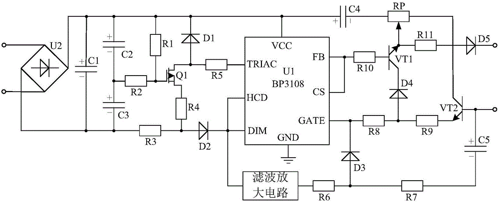
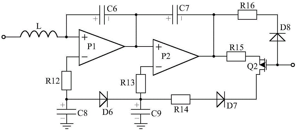
[0018] like figure 1 , 2 As shown, the LED dimming drive system based on the filter amplifier circuit of the present invention is mainly driven by the driver chip U1, resistor R5, resistor R6, capacitor C4, diode D1, diode D3, field effect tube power supply circuit, filter amplifier circuit and triode Circuit composition. Specifically, the P pole of the diode D1 is connected to the TRIAC pin of the driver chip U1 through the resistor R5, and its N pole is connected to the VCC pin of the driver chip U1. The FET power supply circuit is respectively connected to the P pole of the diode D1 and the DIM pin of the driving chip U1. The P pole of the diode D3 is connected to the DIM pin of the driver chip U1 through the resistor R6 and the filter amplifier circuit sequentially, and its N pole is connected to the GATE pin of the driver chip U1. The triode drive circuit is connected to the P pole and N pole of the diode D3 and the FB pin of the drive chip U1 respectively. The anode ...


PUM


Abstract

The invention discloses an LED light modulation driving system based on a filtering amplification circuit. The system is characterized by mainly consisting of a driving chip U1, a resistor R5, a resistor R6, a capacitor C4, a diode D1, a diode D3, a field effect transistor power supply circuit, the filtering amplification circuit and a triode driving circuit. The system, by use of a BP3108 integrated chip and through combination with a peripheral circuit, can control resistance change of a sliding rheostat RP, can adjust brightness of an LED light source according to application needs and satisfies customized demands of people, thereby being suitable for promotion and application.

Description

technical field [0001] The invention relates to a driving system, in particular to an LED dimming driving system based on a filter amplifier circuit. Background technique [0002] With the development of society and the improvement of living standards, people's minds have also been fully liberated. Nowadays, people are very individualized, have their own unique insights into the cognition of objects, and have different needs for things. Similarly, the sensitivity to light is not necessarily the same. Moreover, due to the increasing abundance of electronic products, people's excessive eye use is becoming more and more serious, and the degree of damage to the eyes is different, and the sensitivity to light is also different. Most of the LED light sources currently on the market cannot be dimmed, so they cannot meet people's individual needs. Contents of the invention [0003] The purpose of the present invention is to overcome the defect that most of the LED light sources ...

Claims


Application Information

Patent Timeline
Patent Type & Authority Applications(China)
IPC IPC(8): H05B37/02H03F3/20H05B45/10H05B45/36
CPCH03F3/20H05B47/10
Inventor 不公告发明人
Owner CHENGDU HANXING TECH CO LTD
Why Eureka
Try Eureka