Unlock instant, AI-driven research and patent intelligence for your innovation.
Two-degree of freedom micropositioning platform
What is Al technical title?
Al technical title is built by PatSnap Al team. It summarizes the technical point description of the patent document.
A technology of micro-positioning platform and degree of freedom, which is applied to the parts of the instrument, instruments, etc., can solve the problems of reduced coupling and large size, and achieve the effects of reduced coupling, small size and high positioning accuracy
Active Publication Date: 2016-10-26
KUNMING UNIV OF SCI & TECH
View PDF6 Cites 9 Cited by
Summary
Abstract
Description
Claims
Application Information
AI Technical Summary
This helps you quickly interpret patents by identifying the three key elements:
Problems solved by technology
Method used
Benefits of technology
Problems solved by technology
[0003] The invention provides a two-degree-of-freedom micro-positioning platform, which is used to solve the problem of large volume of traditional equipment, and at the same time reduce the coupling when moving in the X direction and the Y direction
Method used
Image
Click on the blue label to locate the original text in one second.
Reading with bidirectional positioning of images and text.
Examples
Embodiment 1
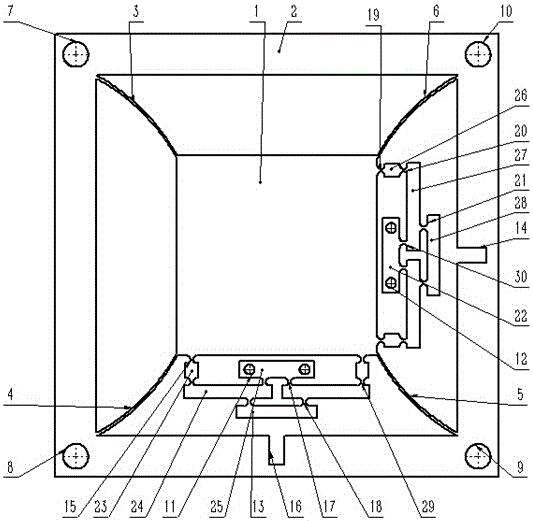
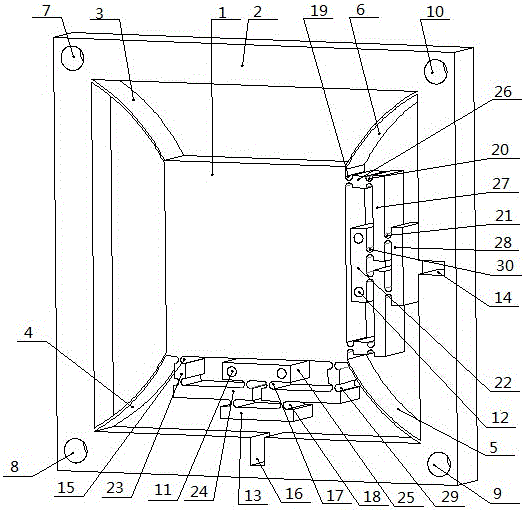
[0019] Embodiment 1: as Figure 1-3 As shown, a two-degree-of-freedom micro-positioning platform includes a motion platform 1, a base 2, an arc-shaped guiding mechanism I3, an arc-shaped guiding mechanism II4, an arc-shaped guiding mechanism III5, an arc-shaped guiding mechanism IV6, fixing bolt holes I7, Fixing bolt hole Ⅱ8, fixing bolt hole Ⅲ9, fixing bolt hole Ⅳ10, lever fixing bolt hole Ⅰ11, lever fixing bolt hole Ⅱ12, Y direction lever Ⅰ13, X direction piezoelectric ceramic drive rectangular slot 14, Y direction flexible hinge Ⅰ15, Y direction Rectangular slot 16 for the piezoelectric ceramic driver in the direction, Y direction flexible hinge II 17, Y direction flexible hinge III 18, X direction flexible hinge I 19, X direction flexible hinge II 20, X direction flexible hinge III 21, X direction lever I 22, Y direction lever II 23, Y direction lever Ⅲ24, Y direction lever Ⅳ25, X direction lever Ⅱ26, X direction lever Ⅲ27, X direction lever Ⅳ28, Y direction flexible hinge...
Embodiment 2
[0024] Embodiment 2: as Figure 1-3 As shown, a two-degree-of-freedom micro-positioning platform includes a motion platform 1, a base 2, an arc-shaped guiding mechanism I3, an arc-shaped guiding mechanism II4, an arc-shaped guiding mechanism III5, an arc-shaped guiding mechanism IV6, fixing bolt holes I7, Fixing bolt hole Ⅱ8, fixing bolt hole Ⅲ9, fixing bolt hole Ⅳ10, lever fixing bolt hole Ⅰ11, lever fixing bolt hole Ⅱ12, Y direction lever Ⅰ13, X direction piezoelectric ceramic drive rectangular slot 14, Y direction flexible hinge Ⅰ15, Y direction Rectangular slot 16 for the piezoelectric ceramic driver in the direction, Y direction flexible hinge II 17, Y direction flexible hinge III 18, X direction flexible hinge I 19, X direction flexible hinge II 20, X direction flexible hinge III 21, X direction lever I 22, Y direction lever II 23, Y direction lever Ⅲ24, Y direction lever Ⅳ25, X direction lever Ⅱ26, X direction lever Ⅲ27, X direction lever Ⅳ28, Y direction flexible hinge...
PUM
Abstract
The invention relates to a two-degree of freedom micropositioning platform, and belongs to the field of micro / nano electromechanical systems. An X-direction lever IV is connected with an X-direction lever III through an X-direction flexible hinge III. The X-direction lever III is connected with an X-direction lever II through an X-direction flexible hinge II. The X-direction lever II is connected with a movement platform through an X-direction flexible hinge I. The X-direction lever III is also connected with an X-direction lever I through an X-direction flexible hinge IV. A Y-direction I is connected with a Y-direction lever III through a Y-direction flexible hinge III. The Y-direction lever III is connected with a Y-direction lever II through a Y-direction flexible hinge IV. The Y-direction lever II is connected with the movement platform through a Y-direction flexible hinge I. The Y-direction lever III is also connected with a Y-direction lever IV through a Y-direction flexible hinge II. The two-degree of freedom micropositioning platform is compact in structure, and small in size, and coupling in moving in the X direction and Y direction is effectively reduced.
Description
technical field [0001] The invention relates to a two-degree-of-freedom micro-positioning platform, which belongs to the field of micro / nano electromechanical systems. Background technique [0002] Micro-positioning platform technology has a wide range of applications in precision manufacturing, ultra-precision measurement, micro-operation and many other fields. At present, with the continuous development of the above-mentioned fields, the requirements for positioning accuracy are getting higher and higher. At the same time, the requirements for strokes have also developed from the original tens of microns to one hundred microns and above. However, the traditional large-stroke micro-positioning platform generally has the disadvantages of being too large and the platform is not easy to process. For a platform with two degrees of freedom, there is generally an input-output coupling problem, which affects the positioning accuracy, and the decoupling problem needs to be conside...
Claims
Application Information
Patent Timeline
Application Date:The date an application was filed.
Publication Date:The date a patent or application was officially published.
First Publication Date:The earliest publication date of a patent with the same application number.
Issue Date:Publication date of the patent grant document.
PCT Entry Date:The Entry date of PCT National Phase.
Estimated Expiry Date:The statutory expiry date of a patent right according to the Patent Law, and it is the longest term of protection that the patent right can achieve without the termination of the patent right due to other reasons(Term extension factor has been taken into account ).
Invalid Date:Actual expiry date is based on effective date or publication date of legal transaction data of invalid patent.
