Micro clamp device with clamping and twisting functions

A micro-clamp, functional technology, applied in the direction of manufacturing tools, metal processing, metal processing equipment, etc., can solve the problems of vacuum suction equipment such as gas leakage, clamping failure, optical fiber sliding, etc., to reduce difficulty and reduce unreliability , Compact and concise layout

Inactive Publication Date: 2013-10-02
BEIHANG UNIV
View PDF13 Cites 17 Cited by
  • Summary
  • Abstract
  • Description
  • Claims
  • Application Information

AI Technical Summary

Problems solved by technology

In angle clamping, because the clamping end has a certain inclination angle, when clamping an optical fiber with a regular geometry, it is easy to cause the optical fiber to slip; vacuum suction clamping is mainly used for operations on a plane, and objects with irregular planes are likely to cause Air leakage from vacuum suction equipment, which in turn leads to clamping failure

Method used


Image

  • Micro clamp device with clamping and twisting functions
  • Micro clamp device with clamping and twisting functions
  • Micro clamp device with clamping and twisting functions

Examples


Embodiment Construction

[0039] The present invention will be further described in detail below in conjunction with the accompanying drawings.

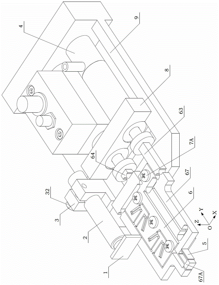
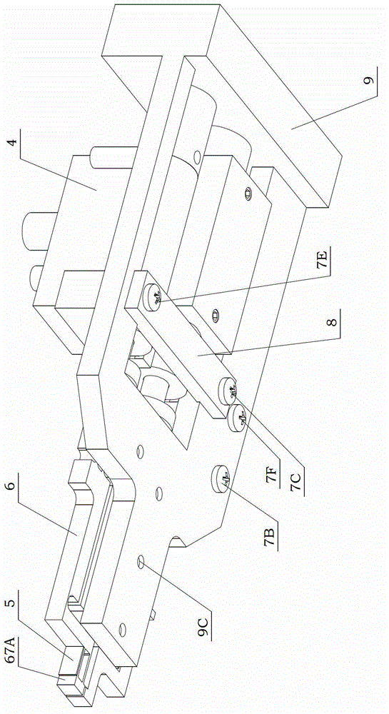
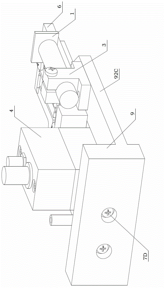
[0040] see figure 1 , Figure 1A , Figure 1B Shown, a kind of micro gripper device with clamping and rubbing function of the present invention, this device includes following parts:

[0041] Displacement measurement plate 1: pasted on the capacitive sensor 2, as the detection object of the capacitive sensor 2, it is used to detect the rubbing displacement of the sixth rigid beam 66 of the micro gripper 6 in the Y-axis direction. The displacement of the micro-clamp 6 in the X-axis direction of the present invention is reflected by the magnitude of the force measured by the force-measuring strain gauge 5 .

[0042] Capacitive sensor 2: used to detect the displacement of the micro gripper 6 in the Y-axis direction. In the present invention, the capacitive sensor 2 is a CPL190C8-2.0 type sensor.

[0043] The first fixing base 3: used for fixing and installin...


PUM


Abstract

The invention discloses a micro clamp device with clamping and twisting functions. The micro clamp device comprises a base, fixed seats, a micro clamp, a displacement measurement plate, a capacitive sensor, a force measurement strain gauge and a piezoelectric ceramic driver, wherein the displacement measurement plate is adhered to the capacitive sensor; the capacitive sensor is arranged on one of the fixed seats; the force measurement strain gauge is arranged on the micro clamp; and the fixed seats, the micro clamp and the piezoelectric ceramic driver are arranged on the base. The micro clamp device adopts a flexible hinge and an asymmetric structure, has two degrees of freedom, completes clamping and rotary twisting operation of an optical fiber by cooperation of two clamp heads, and is richer and more flexible in function.

Description

technical field [0001] The invention relates to a clamping tool, more particularly, a micro-clamp device suitable for assembling MEMS optical switches with clamping and rubbing functions. Background technique [0002] The assembly of MEMS optical switches is a micromanipulative process that integrates optical fibers with silicon chips. However, due to the small size of the light beam, about 100 microns, and the high assembly tolerance requirements with the silicon chip, a high-precision microgripper is required here for precise micromanipulation. However, the traditional micro-gripper can complete the grasping of the optical fiber and put it into the input and output slots on the chip accurately, but the coupling efficiency of the optical path in the assembly process of the MEMS optical switch is also the first factor to be considered, that is, the input Phase alignment with the fiber in the output slot, which is difficult to achieve with conventional microgrippers. [000...

Claims


Application Information

Patent Timeline
Patent Type & Authority Applications(China)
IPC IPC(8): B23P19/00B23Q7/04
Inventor 陈伟海石晓辉陈文杰蒋俊张建斌
Owner BEIHANG UNIV
Why Eureka
Try Eureka