
High current rotary indoor high voltage isolating switch

An isolating switch and rotary technology, applied in electrical switches, high-voltage air circuit breakers, air switch parts, etc., can solve the problems of decreased electrical conductivity, heat of contact fingers and bases, and increased temperature rise of high-voltage isolating switches. Kinetic thermal stability, good electrical conductivity, the effect of improving reliability

Active Publication Date: 2018-08-21
镇江市丹高电器有限公司
View PDF6 Cites 0 Cited by
  • Summary
  • Abstract
  • Description
  • Claims
  • Application Information

AI Technical Summary

Problems solved by technology

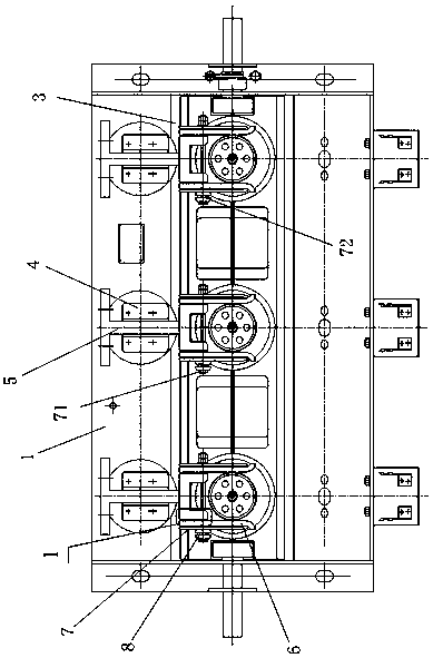
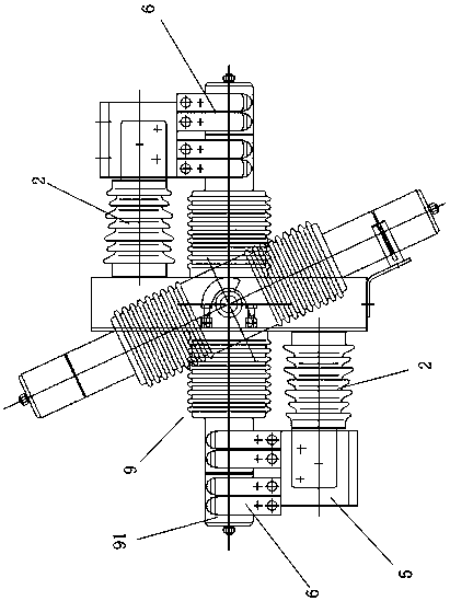
Since the iron clamp 3 and the iron plate chassis 1 around the casing 9 are ferromagnetic materials, eddy current heating will be generated under the action of the three-phase alternating magnetic field, which seriously affects the service life of the iron clamp 3 and the iron plate chassis 1
The high-voltage isolating switch uses the hemispherical contact finger 61 at the upper end of the contact finger 6 to be embedded in the contact socket 51 at the lower end of the contact seat 5 for current transmission. When the high-voltage isolating switch is running with electricity, it has an adsorption effect on dust in the air. Falling into the contact socket 51, resulting in a rapid decline in conductivity, eventually causing the contact finger contact seat to heat up
On the other hand, the resistance between the contact fingers 6 on both sides of the contact seat 5 and the contact seat 5 is in an unbalanced state where one side is large and the other side is small. When a potential difference is generated, the current will pass through the long screw 71 in the middle of the contact fingers 6. Cause the long screw 71 to generate heat; in the long run, the long screw 71 will eventually break due to heat, and the high-voltage isolating switch will be burned
In addition, the conductive pipe 91 and the bushing 9 are fixedly connected with epoxy resin adhesive, and the heat inside the conductive pipe 91 cannot be dissipated, which will increase the temperature rise of the high-voltage isolating switch.

Method used


Image

  • High current rotary indoor high voltage isolating switch
  • High current rotary indoor high voltage isolating switch
  • High current rotary indoor high voltage isolating switch

Examples


Embodiment Construction

[0018] The present invention will be further described below in conjunction with drawings and embodiments.

[0019] Such as Figure 4 As shown, the present invention includes a stainless steel chassis 10, an aluminum clip 20 and a three-phase conductive unit 30, the stainless steel chassis 10 is vertically arranged, the three-phase conductive units 30 are arranged side by side on the stainless steel chassis 10, the aluminum clip 20 is arc-shaped, and the In the middle of the three-phase conduction unit 30 . Such as Figure 5 As shown, each phase conductive unit 30 includes two contact seats 31, a bushing 32 with a conductive tube 321 and two sets of contact pieces 33. The two sets of contact pieces 33 are respectively located at the upper and lower parts of the left and right sides of the stainless steel chassis 10. And the openings correspond to the positions of the two ends of the conductive tube 321 one by one.

[0020] Such as Figure 4 As shown, the contact seat 31 is...


PUM


Abstract

The invention discloses a high current rotary indoor high-voltage isolating switch which comprises a stainless steel chassis, an aluminum clamp and three phases of conducting units arranged on the stainless steel chassis side by side. Each phase of the conducting units comprises two contact seats, a sleeve pipe with a conductive pipe, and two groups of contact piece groups which are at the upper and lower part of the two sides of the stainless steel chassis, and the contact piece groups are corresponding to two ends of the conductive pipe. The contact seat is square, each group of contact piece group comprises multiple rows of copper fingers, a support seat and multiple pairs of stainless steel support plates, one end of each of the copper fingers in a parallel arrangement is fixed between the contact seat and the support seat, the middle parts of the multiple pairs of stainless steel support plates are fixed at two sides of one end of the contact seat through elastic pressing mechanisms. The contact piece groups of the invention have elasticity and good conductivity, the dynamic thermal stability of the switch is increased according to a groove magnetic lock plate, the reliability is improved, and the working life of a high voltage switch cabinet is prolonged.

Description

technical field [0001] The invention relates to a high-current isolating switch, in particular to a high-current rotary indoor high-voltage isolating switch suitable for a box-type fixed high-voltage switchgear with an operating current above 3150A, and belongs to the technical field of high-voltage electrical appliances. Background technique [0002] Existing high-current rotary high-voltage disconnectors such as Figure 1 ~ Figure 3 As shown, it includes iron plate base frame 1, post insulator 2, iron clip 3, clamp seat 4, contact seat 5 in the shape of "I", several rows of contact fingers 6, magnetic lock plate 7, compression spring 8 and a conductive The bushing 9 of the pipe 91 and the post insulator 2 are fixed on the iron plate chassis 1 by bolts. At the outer end of the post insulator 2, the contact seat 5 is fixed on it by the clamp seat 4. Four rows of contact fingers 6 are arranged on both sides of the contact seat 5 respectively, and a magnetic lock plate 7 is p...

Claims


Application Information

Patent Timeline
Patent Type & Authority Patents(China)
IPC IPC(8): H01H31/02
CPCH01H31/023H01H31/026
Inventor 张宝忠成方元丁声飞
Owner 镇江市丹高电器有限公司
Learn More