Tool special for assembling and disassembling contact finger of disconnecting switch

A technology of isolating switches and special tools, applied in electrical switches, electrical components, circuits, etc., can solve the problems of uneven force on the tooth plate, occupying overhaul time, increasing DC resistance, etc., to reduce physical labor intensity, improve The effect of shortening equipment commissioning rate and assembly time

Active Publication Date: 2012-11-14
STATE GRID HUNAN ELECTRIC POWER CO LTD MAINTENANCE CO +2
View PDF5 Cites 8 Cited by
  • Summary
  • Abstract
  • Description
  • Claims
  • Application Information

AI Technical Summary

Problems solved by technology

[0003] However, during the assembly process of free-hand disassembly and assembly and disassembly of the extension rod at the tail, the two pins are easy to fall off; the tooth plate is easily deformed due to uneven force; finger spread
These phenomena make it difficult to cooperate with the contact fingers, compression springs, pins, and tooth plates; in addition, the strength of the spring after replacement is greater than that of the spring before replacement. When installing, the opening of the contact finger is difficult to reach the opening size required for the conductive rod to enter the contact finger smoothly
These factors make the assembly process take up a lot of maintenance time, and the first-time assembly success rate is very low
In addition, in the process of dismantling and assembling, the spring is likely to be damaged, so that the pressure of the contact finger is not enough, the DC resistance increases, and the contact heating occurs.

Method used


Image

  • Tool special for assembling and disassembling contact finger of disconnecting switch
  • Tool special for assembling and disassembling contact finger of disconnecting switch
  • Tool special for assembling and disassembling contact finger of disconnecting switch

Examples


Embodiment Construction

[0024] Various embodiments of the present invention will be described in detail below in conjunction with the accompanying drawings.

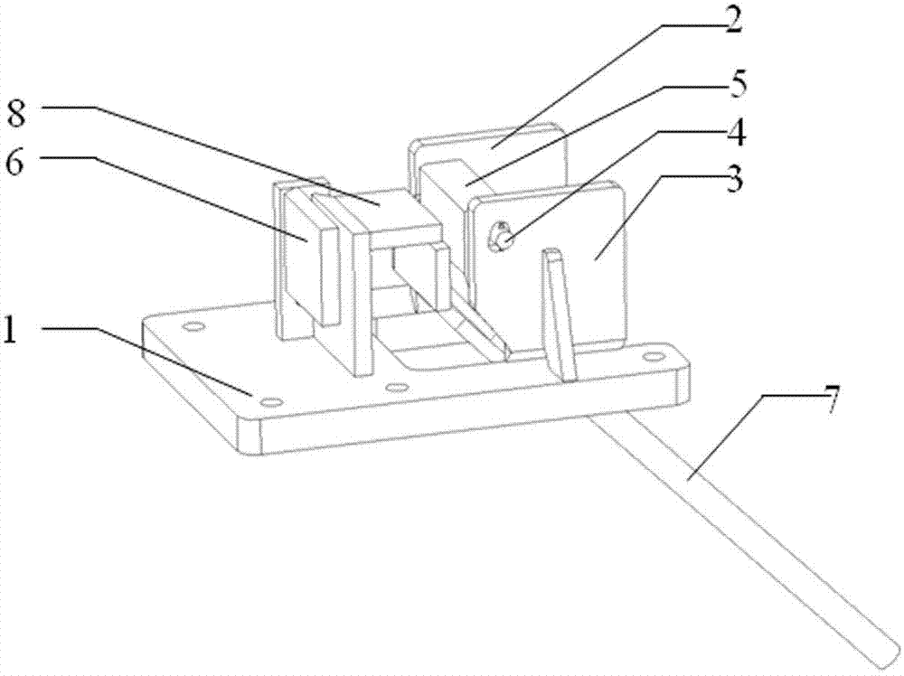
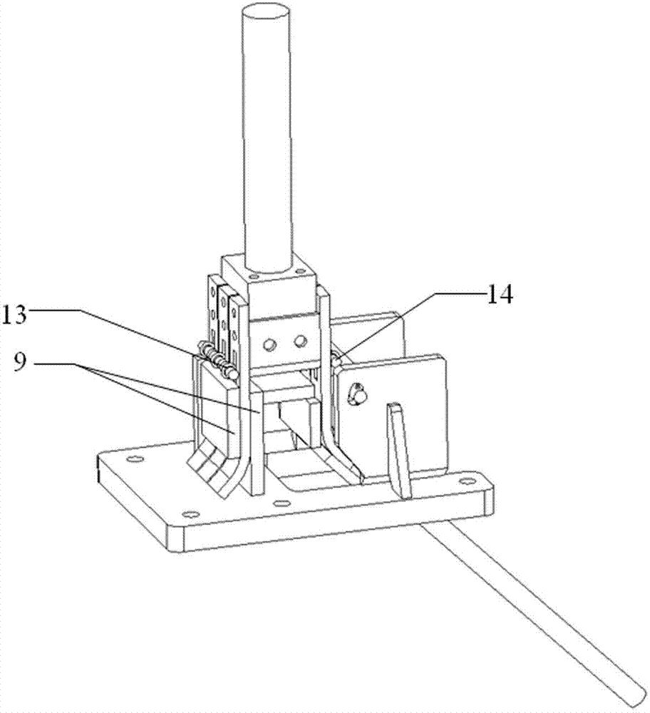
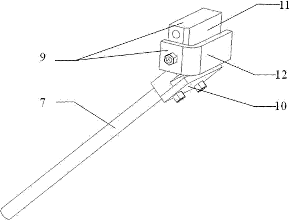
[0025] see Figure 1-4 . Figure 1-4 Example 1 of the present invention is shown.

[0026] The present invention comprises a bottom plate 1 , a first vertical plate 2 , a second vertical plate 3 , a rotating shaft 4 , a first contact finger clamping device 5 , a second contact finger clamping device 6 , a handle 7 and a tooth plate baffle 8 .

[0027] Wherein, the bottom plate 1 is U-shaped, and the first vertical plate 2 and the second vertical plate 3 are welded on the right sides of the bottom plate 1 and arranged oppositely. The through hole and the outer side are provided with ribs; the rotating shaft 4 is installed between the first vertical plate 2 and the second vertical plate 3 through the through hole, and is fixed by a fixed pin; the first contact finger clamping device 5 is set on the rotating shaft 4; in order to fix the first f...


PUM


Abstract

The invention discloses a tool special for assembling and disassembling a contact finger of a disconnecting switch. The tool comprises a bottom plate, a first upright plate, a second upright plate, a rotating shaft, a first contact finger clamping device, a handle, a second contact finger clamping device and a toothed plate baffle plate, wherein the first upright plate and the second upright plate are fixedly and oppositely arranged on the two sides of the right side of the bottom plate; the rotating shaft penetrates through the first upright plate and the second upright plate; the first contact finger clamping device is sleeved on the rotating shaft; the handle is fixedly arranged on the first contact finger clamping device; the second contact finger clamping device is fixedly arranged on the left side of the bottom plate; the toothed plate baffle plate is arranged between the first contact finger clamping device and the second contact finger clamping device; the first contact finger clamping device and the second contact finger clamping device are provided with clamping components used for clamping the contact finger; and when the handle is rotated, the first contact finger clamping device can be rotated along the rotating shaft. By adopting the tool, the cooperation among the contact finger, a compression spring, a pin and a toothed plate can be enhanced, and an opening of the contact finger can be pressed open with less effort.

Description

technical field [0001] The invention relates to a contact finger assembly and disassembly tool for an isolating switch, in particular to a special tool for assembling and disassembling a contact finger of a high-voltage isolating switch in a power system. Background technique [0002] At present, due to the heating effect of the contact of the GW5-126 isolating switch, after a period of use, the contact fingers need to be disassembled and overhauled. The methods for assembling and disassembling the GW5-126 disconnector contact fingers include disassembly by hand, disassembly by adding an extension rod at the tail and disassembly by using an installation and disassembly device. Free-hand disassembly refers to directly pressing the opening of the contact finger to a certain angle manually, and then assembling or disassembling the conductive rod; adding an extension rod to the tail refers to adding an extension rod to the tail of one end of the contact finger, and using the ext...

Claims


Application Information

Patent Timeline
Patent Type & Authority Applications(China)
IPC IPC(8): H01H11/00
Inventor 王智弘褚玉杰刘盛祥宋兴荣沈忠伟李进
Owner STATE GRID HUNAN ELECTRIC POWER CO LTD MAINTENANCE CO
Why Eureka
Try Eureka