

Tubular busbar connection structure
A technology for connecting structure and tube busbar, applied in the direction of connection, connecting contact material, clamping/spring connection, etc., can solve the problems of multiple elastic contact fingers, elastic contact finger damage, unfavorable tube busbar sealing, etc.
- Summary
- Abstract
- Description
- Claims
- Application Information
AI Technical Summary
Problems solved by technology
Method used
Image

Examples
Embodiment Construction
[0017] Embodiments of the present invention will be further described below in conjunction with the accompanying drawings.
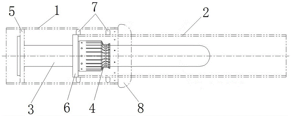
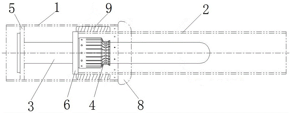
[0018] Specific embodiment 1 of the pipe-female connection fittings of the present invention, such as figure 1 As shown, among them, 1 is the thick tube busbar, 2 is the thin tube busbar, 3 is the contact, 4 is the spring contact finger, 5 is the aluminum terminal board, 6 is the contact seat, 7 is the limit wear-resistant slip ring, 8 is the End cap shield.
[0019] The thin-tube busbar 2 is inserted into the thick-tube busbar 1, and one end of the thin-tube busbar 2 is located in the thick-tube busbar 1, and the two can perform relative plugging and telescopic movements. There is an aluminum terminal board 5 inside the thick tube bus 1 far away from the thin tube bus 2. The aluminum terminal board 5 is arranged in the radial direction of the thick tube bus 1 and conducts with the thick tube bus 1. The contact 3 is installed on the aluminum terminal bo...
PUM
 Abstract
Description
Claims
Application Information