
A serial crankshaftless engine transmission mechanism and an engine having the same

A transmission mechanism and engine technology, applied in the direction of machines/engines, mechanical equipment, etc., can solve the problems of low transmission efficiency, achieve simple maintenance, reduce emissions, and reduce idling speed

Active Publication Date: 2019-03-22
朱晓明
View PDF7 Cites 0 Cited by
  • Summary
  • Abstract
  • Description
  • Claims
  • Application Information

AI Technical Summary

Problems solved by technology

[0008] The present invention provides a serial crankshaftless engine transmission mechanism and an engine with it to solve the above-mentioned technical problems of low transmission efficiency, engine vibration and adjustable compression ratio

Method used


Image

  • A serial crankshaftless engine transmission mechanism and an engine having the same
  • A serial crankshaftless engine transmission mechanism and an engine having the same
  • A serial crankshaftless engine transmission mechanism and an engine having the same

Examples


Embodiment Construction

[0044] The present invention will be further described below in conjunction with the accompanying drawings and embodiments.

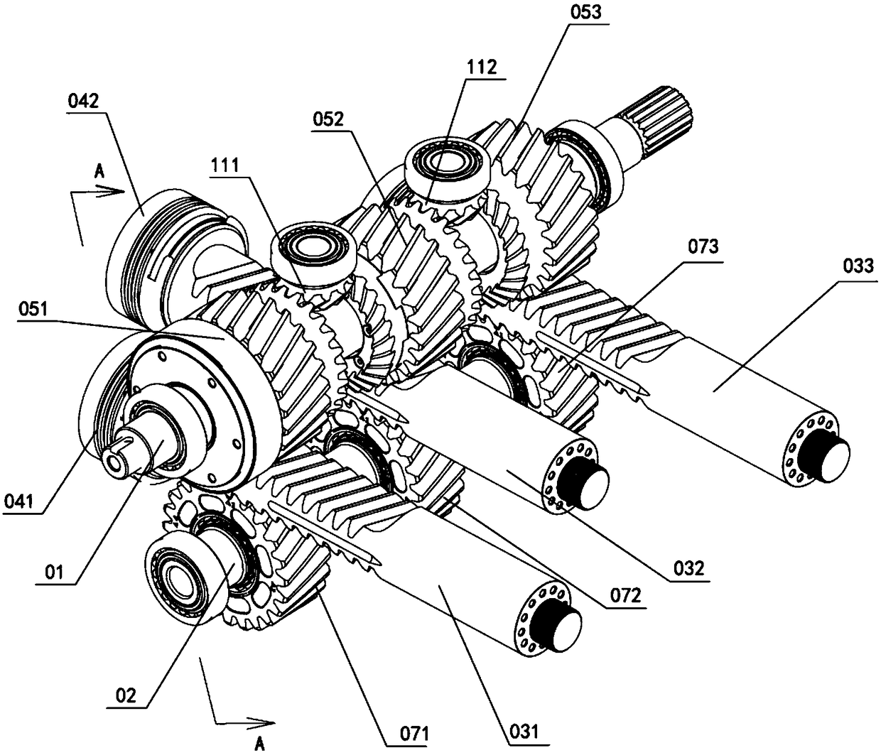
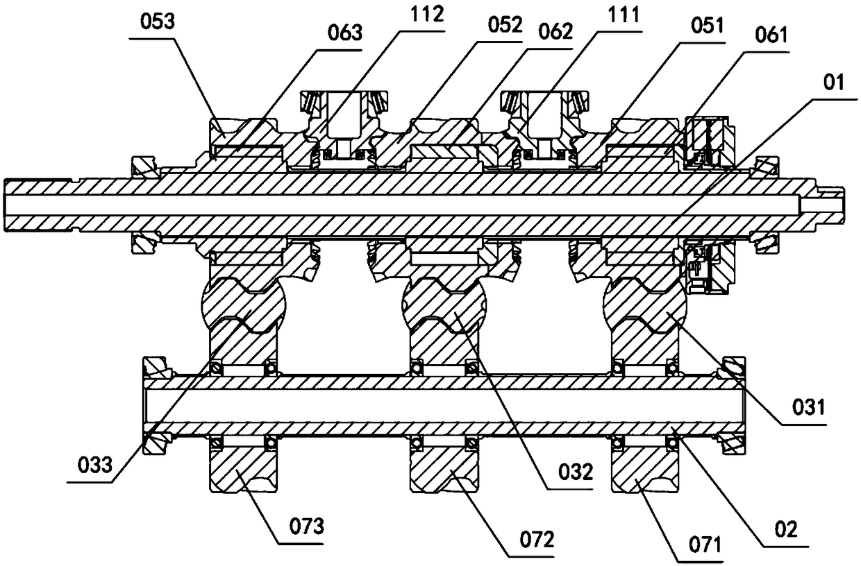
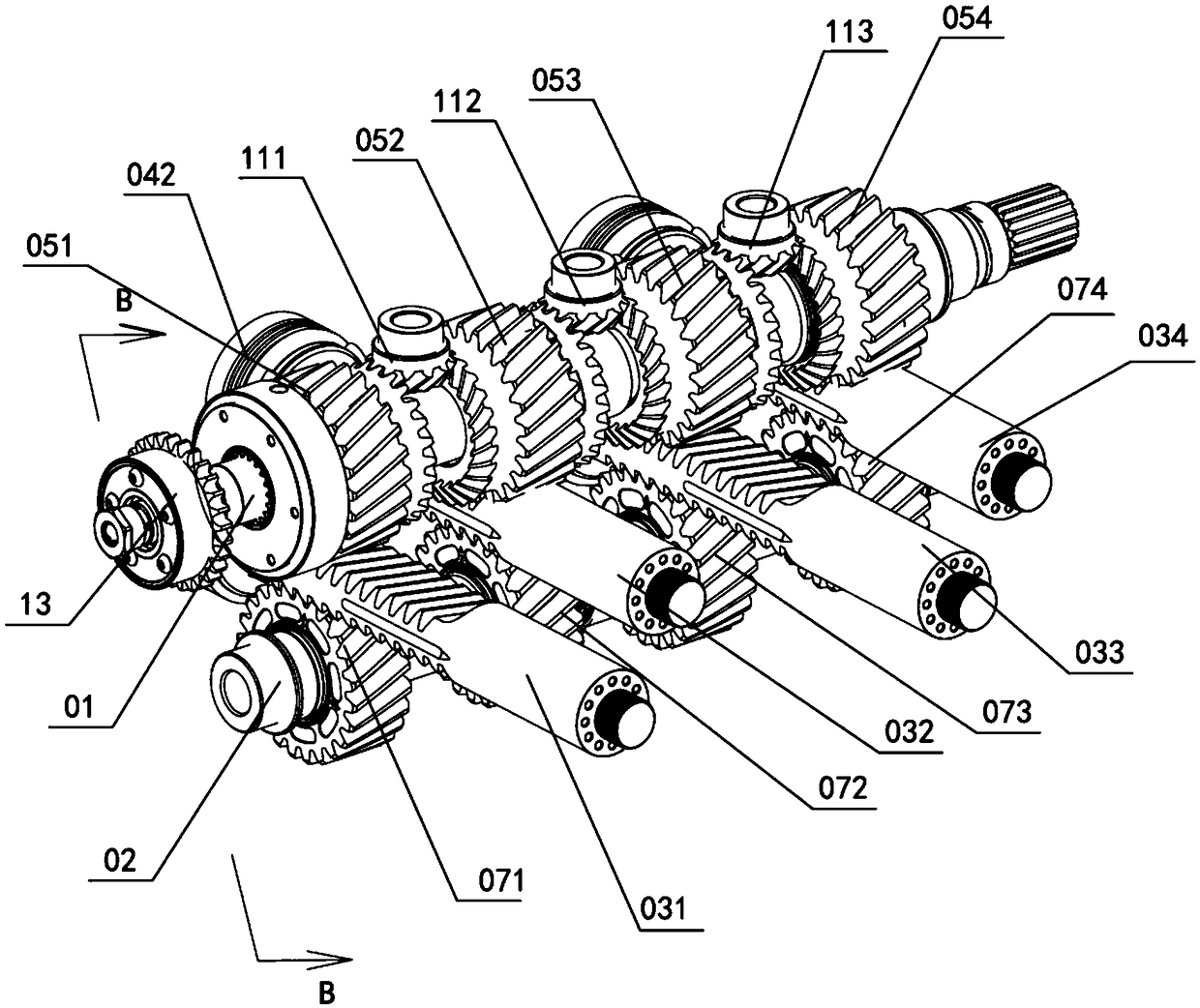
[0045] For the structure diagram of Embodiment 1 of the present invention, see figure 1 and figure 2 , a serial crankshaftless engine transmission mechanism, including a power shaft 01 and a countershaft 02, the power shaft 01 and the countershaft 02 are arranged parallel to each other, and at least three cylinder piston rods are arranged between the power shaft 01 and the countershaft 02, including the first cylinder piston Rod 031, the second cylinder piston rod 032 and the third cylinder piston rod 033; the same end of the three cylinder piston rods, that is, the end of the left end of the illustration is provided with a cylinder piston, and the end of the first cylinder piston rod 031 left end The first cylinder piston 041 is provided, and the second cylinder piston rod 032 is provided with a second cylinder piston 042; one side of each cylinder p...


PUM


Abstract

The invention discloses a series connection non-crankshaft engine transmission mechanism which comprises a power shaft and an auxiliary shaft. At least two air cylinder piston rods are arranged between the power shaft and the auxiliary shaft. Air cylinder pistons are arranged at the end heads of the same ends of the air cylinder piston rods correspondingly. One side of each air cylinder piston rod is engaged with a main gear which is arranged on the power shaft in a sleeving manner through a one-way clutch. The combining directions of the one-way clutches are the same. The other side of each air cylinder piston rod is rotationally connected with the auxiliary shaft through a guiding mechanism. Every two adjacent two main gears are in transmission connection through a reverse transmission mechanism. When one air cylinder piston rod acts, the corresponding main gear rotates, and when the combining directions of the one-way clutches are the same, the main gears corresponding to the power shaft enable the power shaft to rotate to output power through the corresponding one-way clutches. Meanwhile, transmission and reversing of power needed by the stroke of the corresponding air cylinder piston rods are achieved by every adjacent two main gears through the corresponding reverse transmission mechanisms. The transmission mechanism belongs to a free piston type, and therefore a variable compression ratio function is achieved.

Description

technical field [0001] The invention relates to the technical field of engines, in particular to a serial crankshaftless engine transmission mechanism and an engine with the same. At the same time, it has the function of adjustable compression ratio. Background technique [0002] A common engine mixes fuel and air and burns it in its cylinder, and the heat energy released makes the cylinder generate high-temperature and high-pressure gas. The expansion of the gas pushes the piston to do work, and then the mechanical work is output through the crank connecting rod mechanism to drive the driven machine to work. [0003] Adopting the crankshaft-connecting rod mechanism has also become a classic structure of power transmission; but there are still many shortcomings in this mechanism. Low mechanical transmission efficiency: the force of the gas acting on the piston is transmitted to the crankshaft through the connecting rod, and two component forces are generated at the connect...

Claims


Application Information

Patent Timeline
Patent Type & Authority Patents(China)
IPC IPC(8): F02B75/32
CPCF02B75/32
Inventor 朱晓明
Owner 朱晓明
Learn More