Fastening element for a current sensor

A technology of current sensors and fixed components, applied in the direction of inductors, electrical components, only measuring current, etc., can solve problems such as manual work, installation complexity, screw loosening, etc.

Active Publication Date: 2016-11-02
HARTING ELECTRIC GMBH & CO KG
View PDF13 Cites 2 Cited by
  • Summary
  • Abstract
  • Description
  • Claims
  • Application Information

AI Technical Summary

Problems solved by technology

This sinking (counter-sunk) naturally contributes to the compactness of the overall arrangement, but may require some manual work during installation
In addition, there is a fundamental risk with such screw connections that the screws can also loosen again due to prolonged vibrations, such as occur during railway operation
This looseness can of course also be overcome by additional means, for example using specially shaped washers, but this means additional installation complexity
[0007] A disadvantage in this prior art is therefore, inter alia, the relatively large amount of manual work on installation

Method used


Image

  • Fastening element for a current sensor
  • Fastening element for a current sensor
  • Fastening element for a current sensor

Examples


Embodiment Construction

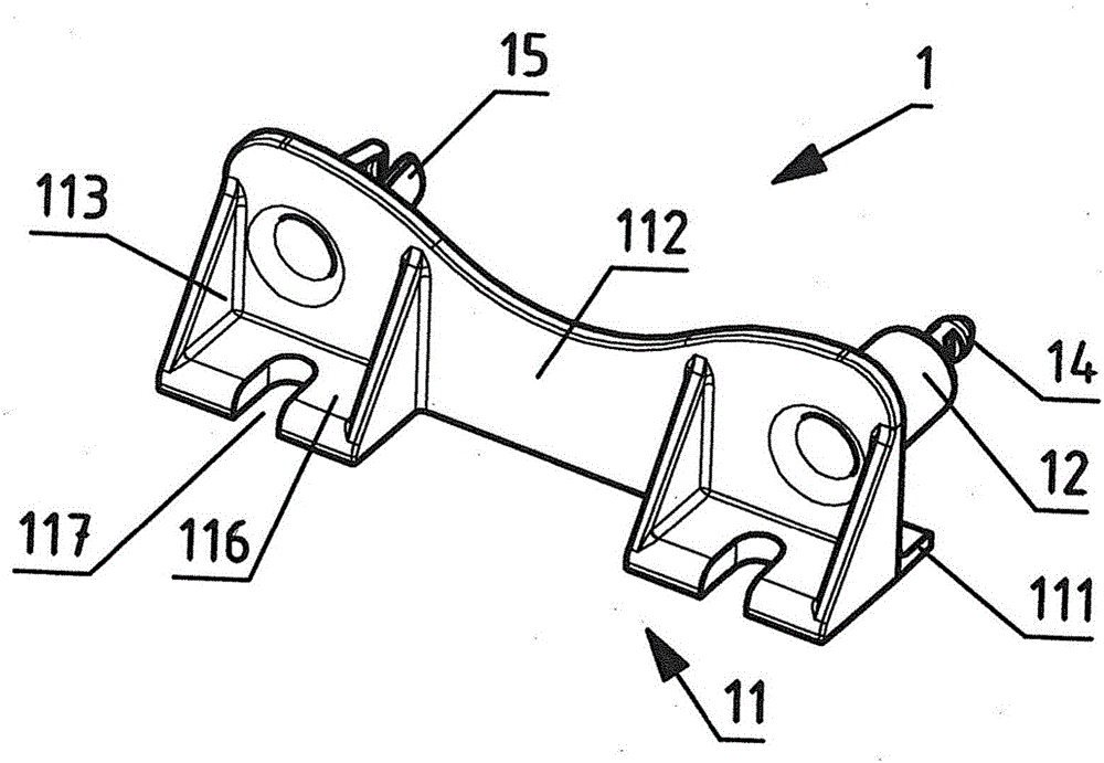
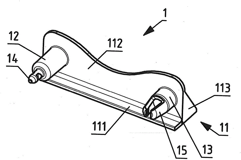
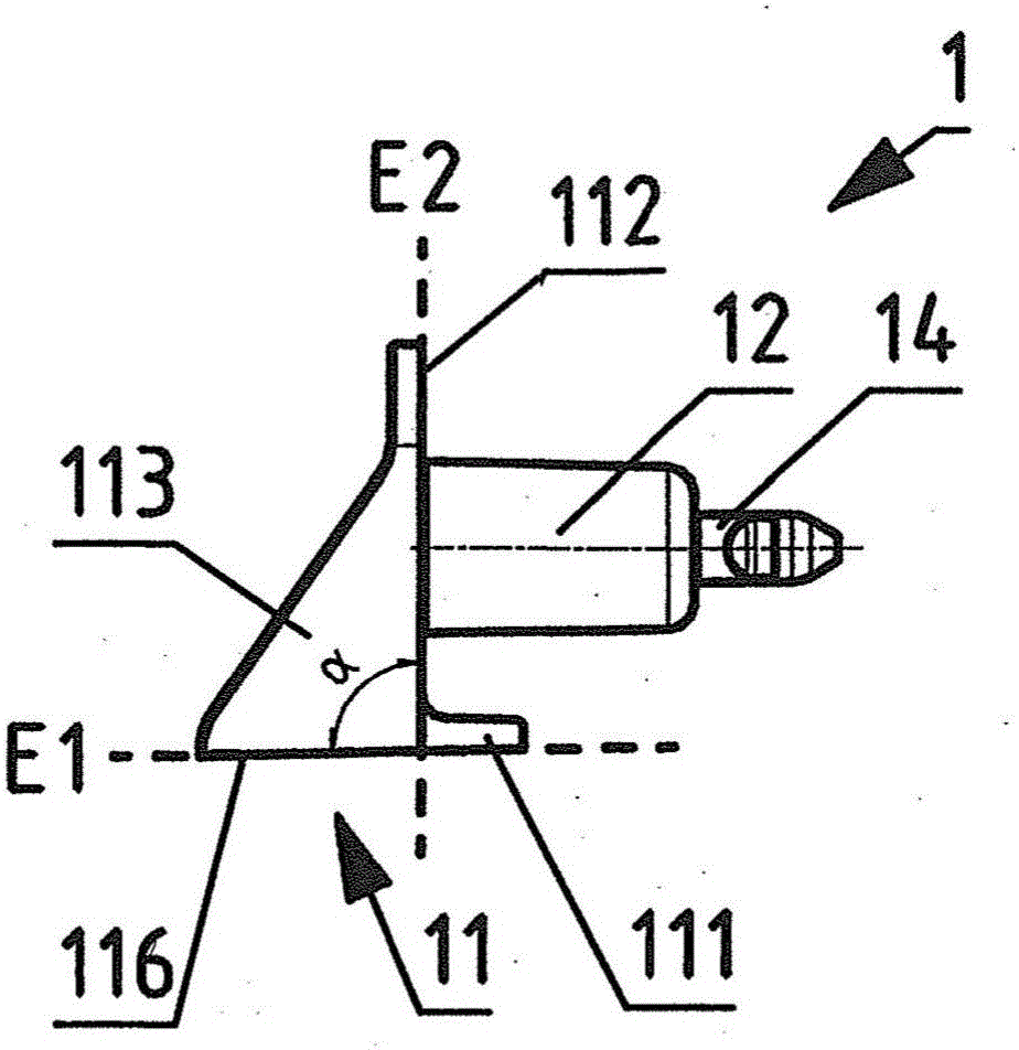
[0041] Figure 1a , 1b , 1c and 1d show different views of the fixing element 1 . The fastening element has a flange area 11 and two latching means, namely a first latching means and a second latching means.

[0042] The flange region 11 is clearly visible in FIG. 1 . This flange area has a seat area for fastening to the fastening surface 3 . This bearing area has bearing slats 111 and two bearing surfaces 116, in Figure 1b The support strips are again clearly visible. Fastening notches 117 can be arranged in each such seat surface 116 , for example for screwing or otherwise fastening to the fastening surface 3 . Advantageously, the flange area 11 has a clamping surface 112 . The support strip 111 , the two support surfaces 116 and the clamping surface 112 adjoin one another and are also connected to one another by a stabilizing surface 113 in order to stabilize their fastening to one another. Each of the two abutment surfaces 116 is connected to the clamping surface 11...


PUM


Abstract

The object of the present invention is to reduce the manual assembly effort of current sensors, and to specify a configuration for a fastening element (1) by means of which a current sensor (2) can be fastened on a fastening surface (3) in both lying and standing positions with the lowest possible effort. The fastening element (1) according to the invention therefore proposes at least one, preferably two, snap-in locking devices and can thus be fastened ("clipped") on to the current sensor with the lowest possible manual effort. For example, two fastening elements (1, 1') according to the invention, with the snap-in locking devices on opposite sides, can be inserted into the same screw passages (23, 24) of the current sensor (2) and, in particular, lock each other in place using the snap-in locking devices in a screw hole (231, 241) belonging to the respective screw passage (23, 24) and thus are held on the current sensor (2).

Description

technical field [0001] The invention relates to a fastening element for a current sensor according to the preamble of independent claim 1 . [0002] Such fastening elements are required to allow the current sensor to be fastened not only horizontally, but alternatively also vertically to the fastening surface. Background technique [0003] EP 1 181 698 B1 discloses a current sensor with two installation positions, which can be fastened vertically or horizontally to a support surface. The current sensor has a housing with a first set of openings for fixing screws to fix the housing horizontally on a support surface, the axis of the fixing screws being perpendicular to the large surface of the housing, wherein for The second set of openings of the fixing screws is used to vertically fix the housing on the support surface, the axis of the fixing screws is perpendicular to the first set of openings that can be used for the screws, and it is characterized in that the current sen...

Claims


Application Information

Patent Timeline
Patent Type & Authority Applications(China)
IPC IPC(8): G01R1/04F16B21/07
CPCF16B21/071F16B21/073G01R1/04G01R15/183G01R15/188H01F27/06H01F38/30G01R19/0092G01R15/18
Inventor A·蒂曼
Owner HARTING ELECTRIC GMBH & CO KG
Why Eureka
Try Eureka