Current measuring method and current measuring device

a current sensor and current measurement technology, applied in the direction of measurement devices, magnetic measurements, instruments, etc., can solve the problems of large current sensor size, noise and excessive input, and restrictions on the mounting of current sensors

Inactive Publication Date: 2006-02-16
ASAHI KASEI ELECTRONICS CO LTD
View PDF7 Cites 121 Cited by
  • Summary
  • Abstract
  • Description
  • Claims
  • Application Information

AI Technical Summary

Benefits of technology

[0027] According to this construction, a magnetic flux generated by a current flowing through the conductor for measurement can easily reach a position symmetrical to the conductor for measurement with respect to the board, which position is on the surface of the board on the side that is opposite to the conductor for measurement. Therefore, by providing the current sensor in this position, the magnetic flux generated by a current flowing through the conductor for measurement can be easily detected by use of the current sensor.
[0029] According to this construction, because a soft magnetic material is provided on an exterior surface of the conductor for measurement on the side that is opposite to an exterior surface facing the surface of the board, the magnetic flux generated by the current flowing through the conductor for measurement can be easily concentrated on the current sensor side by the soft magnetic material.
[0033] According to this construction, because multiple soft magnetic materials are provided between the current sensor and the board, the magnetic flux generated by the current flowing through the conductor for measurement can be easily concentrated on the current sensor side by the multiple soft magnetic materials.
[0035] According to this construction, because the magnetic flux concentrating means is provided between the Hall element and the facing surface, the magnetic flux generated by the current flowing through the conductor for measurement can be easily received by the magnetic flux concentrating means. For this reason, the magnetic flux generated by the current flowing through the conductor for measurement can be effectively concentrated on the magnetic flux sensing surface of the Hall element.
[0037] According to this construction, because the magnetic flux concentrating plates are provided so that surfaces of the magnetic flux concentrating plates are facing the surface of the board, the magnetic flux generated by the current flowing through the conductor for measurement can be easily received by the magnetic flux concentrating plates. For this reason, the magnetic flux generated by the current flowing through the conductor for measurement can be effectively concentrated on the magnetic flux sensing surface of the Hall element.
[0039] According to this construction, because the magnetic flux concentrating plates are spaced so as to be positioned on both sides of a center line of the conductor for measurement as viewed from the direction perpendicular to the plane of the board, the magnetic flux received by the magnetic flux concentrating plates can be effectively concentrated on the magnetic flux sensing surface of the Hall element.

Problems solved by technology

However, because in the first to third conventional examples, the primary side current conductor and the conductor for measurement are directly connected, it is necessary to ensure sufficient electric insulation between a signal line that is provided within the current sensor and used to output sensor signals (hereinafter referred to as the secondary side current conductor) and the conductor for measurement, posing the problem that there are given restrictions to the mounting of the current sensor.
When electric insulation is not sufficient, there is a possibility that noise and excessive input may be transmitted to the side of a circuit that uses sensor signals from the current sensor.
Also, when a current flowing through the conductor for measurement is large, it is necessary to increase the size of the primary side current conductor to adapt to the large current, posing the problem that the current sensor becomes large in size.
Furthermore, when the primary side current conductor and the conductor for measurement are directly connected, heat is generated because a current flows through a contact resistor in the connection part, posing the problem that there is a possibility that if the calorific value is large, the reliability of the current sensor may be impaired.
Similarly, in a current measuring method using a shunt resistor, it is impossible to ensure electric insulation between a signal line to output sensor signals and the conductor for measurement, posing the problem that there are given restrictions to the mounting.
Also, when a current flowing through the conductor for measurement is large, it is necessary to increase the size of a heat sink of the shunt resistor to adapt to the large current, posing the problem that the current sensor becomes large in size.
Furthermore, when the shunt resistor and the conductor for measurement are directly connected, heat is generated because a current flows through the resistor, posing the problem that there is a possibility that if the calorific value is large, the reliability of the current sensor may be impaired.
Furthermore, noncontact current measuring methods by the latest high-sensitivity magnetic sensor such as GMR pose the problems that sufficient accuracy cannot be ensured because the magnetic hysteresis is large, and that attaching accuracy is severe, the mounting place is limited and the direction of a current cannot be detected because it is necessary to use a bias magnet.

Method used


Image

  • Current measuring method and current measuring device
  • Current measuring method and current measuring device
  • Current measuring method and current measuring device

Examples


examples

[0074] Next, examples of the invention will be described by referring to FIG. 5 to FIG. 12.

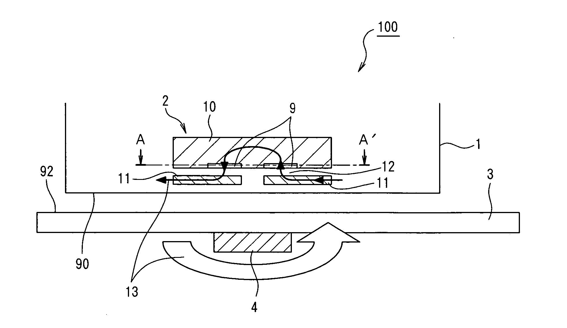
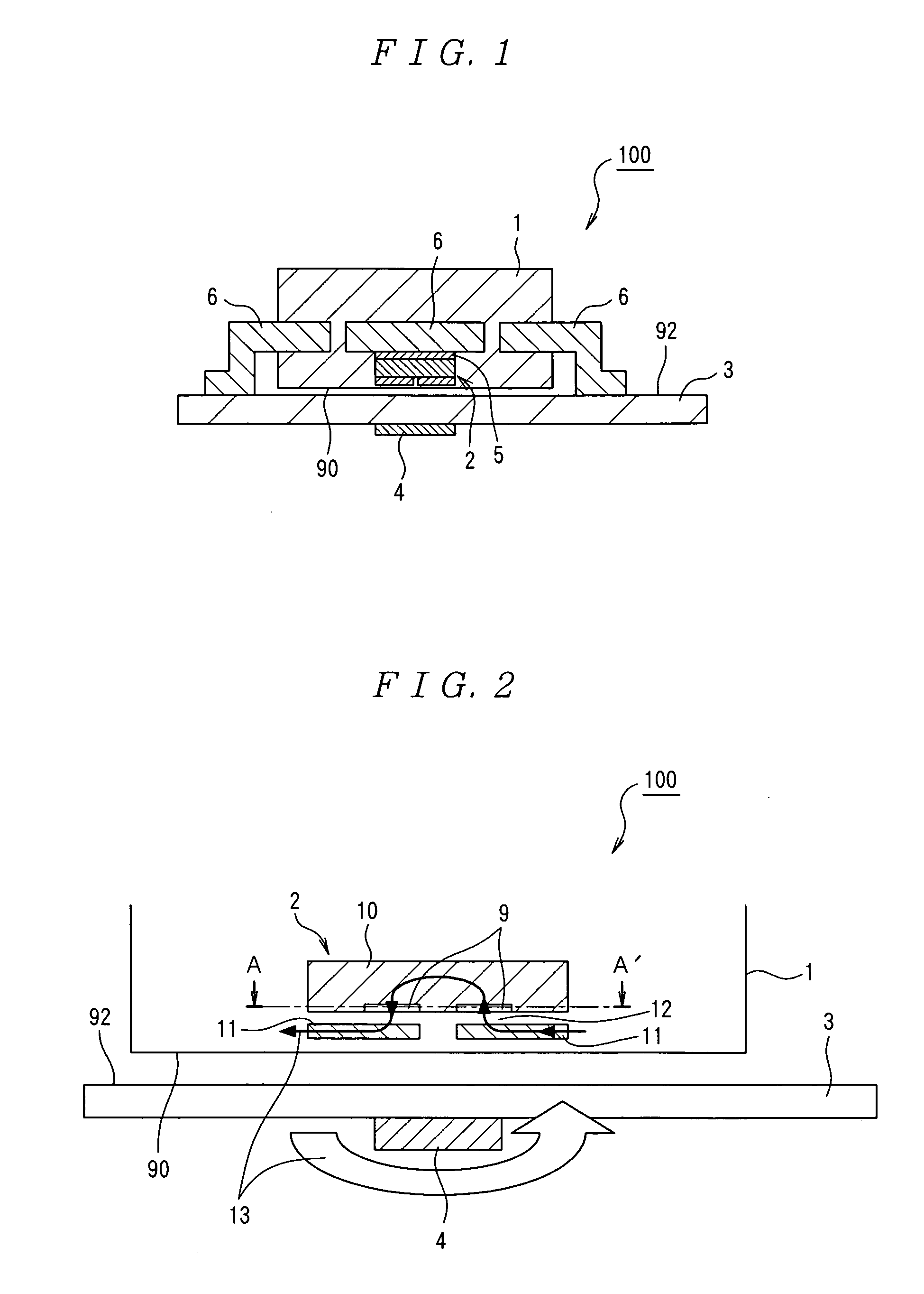
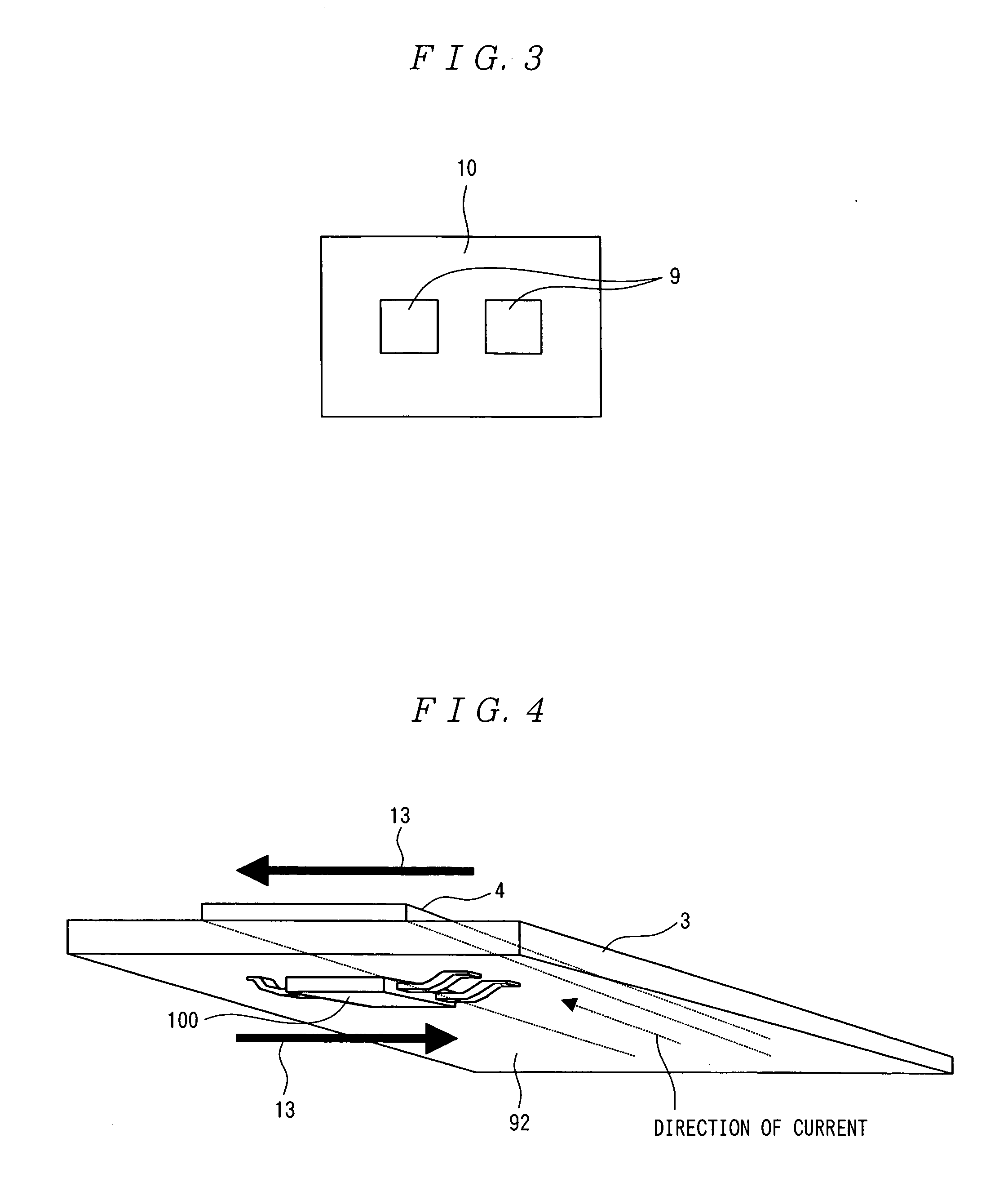
[0075] A conductor for measurement 4 formed from copper coil 35 μm in thickness and 15 mm in width was formed on a printed board 3 having a thickness of 1.6 mm, and a current sensor 100 was mounted on a rear surface 92 and in a position symmetrical to the conductor for measurement 4 with respect to the printed board 3. This mounting enables sufficient electric insulation between the current sensor 100 and the conductor for measurement 4 to be ensured.

[0076] In the current sensor 100, a TSSOP-16 package that has generally found wide use was used as a mold package 1. The thickness of the mold package 1 was about 1 mm, and Hall elements 9 were disposed in positions about 300 μm from the bottom surface so as to come very close to the conductor for measurement 4 as far as possible. On the surface of the Hall element 9 were disposed multiple magnetic flux concentrating plates 11 formed from a soft...


PUM


Abstract

A current measuring method capable of reducing the size of a current sensor while ensuring electric insulation easily and suitable for enhancing reliability by preventing heat generation. A current measuring device comprises a printed board (3) having a conductor for measurement (4), and a noncontact current sensor (100) being mounted on the printed board (3), wherein the current sensor (100) is mounted on the surface (92) of the printed board (3) opposite to the side provided with the conductor for measurement (4). Since the current sensor (100) is mounted on the rear surface (92), electric insulation between the secondary conductor of the current sensor (100) and the conductor for measurement (4) can be ensured relatively easy.

Description

TECHNICAL FIELD [0001] The present invention relates to a method and device for measuring a current flowing through a conductor for measurement on a board by use of a current sensor mounted on the board and, particularly, to a current measuring method and a current measuring device that easily ensure electric insulation, can reduce the size of a current sensor and are suitable for improving reliability by preventing heat generation. BACKGROUND ART [0002] As techniques for measuring a current on a printed board, those using a shunt resistor, a magnetoresistive element or a Hall element have hitherto been widely known. [0003] As techniques for measuring a current by use of a Hall element, there have been known, for example, a current detecting unit disclosed in the Japanese Patent Laid-Open No. 8-233865 (hereinafter referred to as the first conventional example), a current measuring method using a current sensor disclosed in the Japanese Patent Laid-Open No. 10-267965 (hereinafter ref...

Claims


Application Information

Patent Timeline
Patent Type & Authority Applications(United States)
IPC IPC(8): G01R33/07G01R15/20
CPCG01R15/202
Inventor NAGANO, SHUICHISHIBAHARA, KOJIISHIBASHI, KAZUTOSHI
Owner ASAHI KASEI ELECTRONICS CO LTD
Why Eureka
Try Eureka