Power distribution with digital current control

a technology of digital current control and power distribution, which is applied in the direction of constant-current supply dc circuit, process and machine control, instruments, etc., can solve the problems of thermal problems, the current limiter may not be needed, and the current limiter must dissipate substantial power, so as to reduce the cost of the power supply and the power dissipation of the current limiter is minimal

Inactive Publication Date: 2005-01-11
CISCO TECH INC
View PDF14 Cites 130 Cited by
  • Summary
  • Abstract
  • Description
  • Claims
  • Application Information

AI Technical Summary

Benefits of technology

In some preferred embodiments of the present invention, a power supply comprises a voltage source with a current limiter that operates by pulse width modulation (PWM), rather than by variable impedance as in power supplies known in the art. The current limiter receives an input from a current sensor, which senses the current drawn by the load of the power supply, and varies the PWM duty cycle in order to maintain the magnitude of the current within a predetermined limit. Typically, the current limiter comprises a simple switch, such as a transistor, which is opened and closed with the proper frequency and phase to provide the desired PWM. Therefore, the power dissipation of the current limiter is minimal, even when severe current limiting must be applied. A smoothing circuit is coupled between the output of the current limiter and the load, so that the load receives DC current notwithstanding the PWM.
In a preferred embodiment, the method includes determining a temperature of the current limiter while sampling the current, and saving the estimated current limiting characteristic for use in selecting the target setting on a future occasion upon which the current exceeds the predetermined maximum and the current limiter is operating at the determined temperature.

Problems solved by technology

Conventional methods for current limiting of DC power supply output have a number of drawbacks, which are particularly problematic in the context of Power over LAN:When current limiting is needed to prevent an overload, the current-limiting element in the power supply must dissipate substantial power.
Current limiting may be needed not only in fault situations, but also under certain normal operating conditions.
The substantial power dissipation required of the current-limiting element creates thermal problems in the hub.Because an integrating amplifier or digital integrator is used to control the current-limiting element, the response of the element to current changes is typically slow.
On the other hand, reducing the time constant of the integrator can lead to instability and oscillations of the current-limiting impedance.All the terminals that are powered by the hub must be protected individually against over current.
The cost of the hub is therefore increased by the need to provide a separate sampling resistor, current-limiting element and control circuit for each connection in the LAN.

Method used


Image

  • Power distribution with digital current control
  • Power distribution with digital current control
  • Power distribution with digital current control

Examples


Embodiment Construction

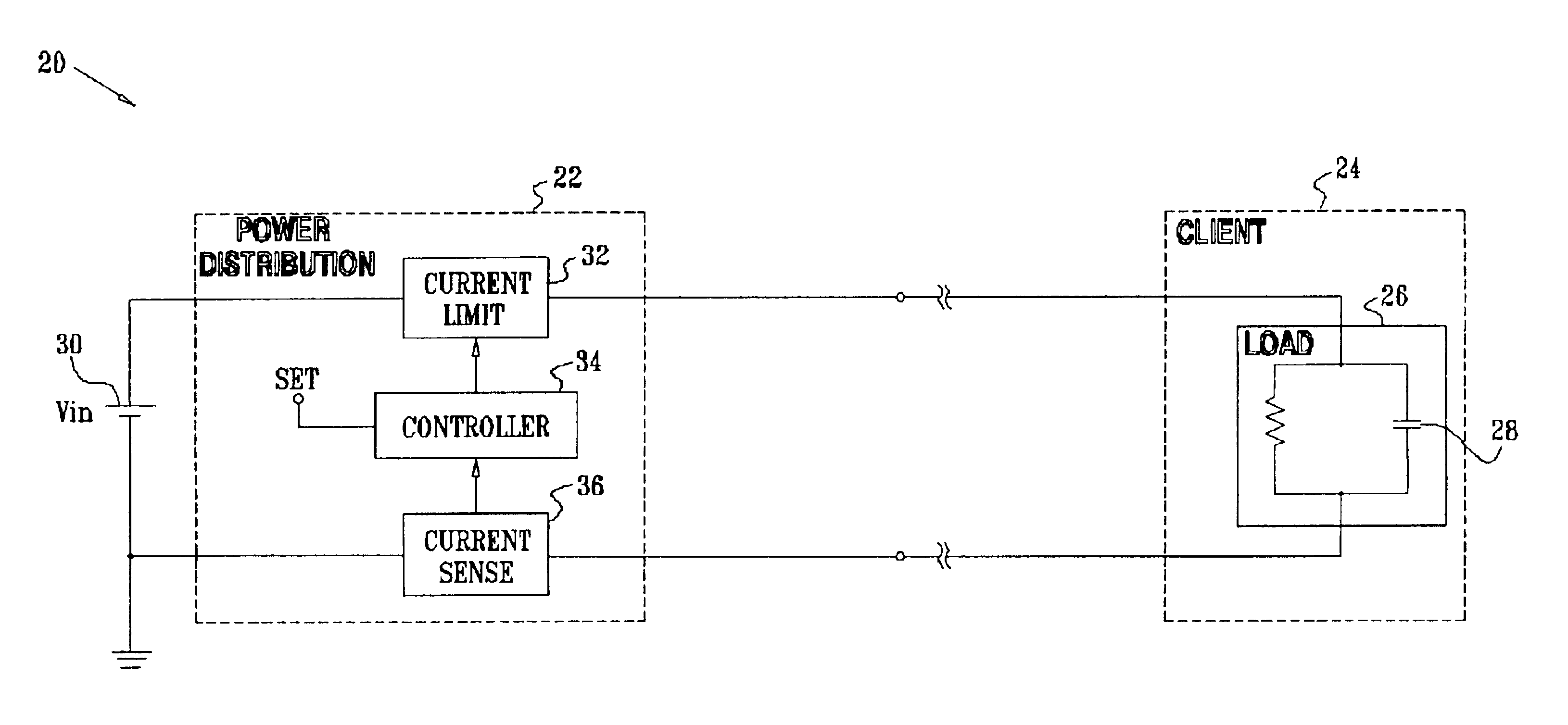
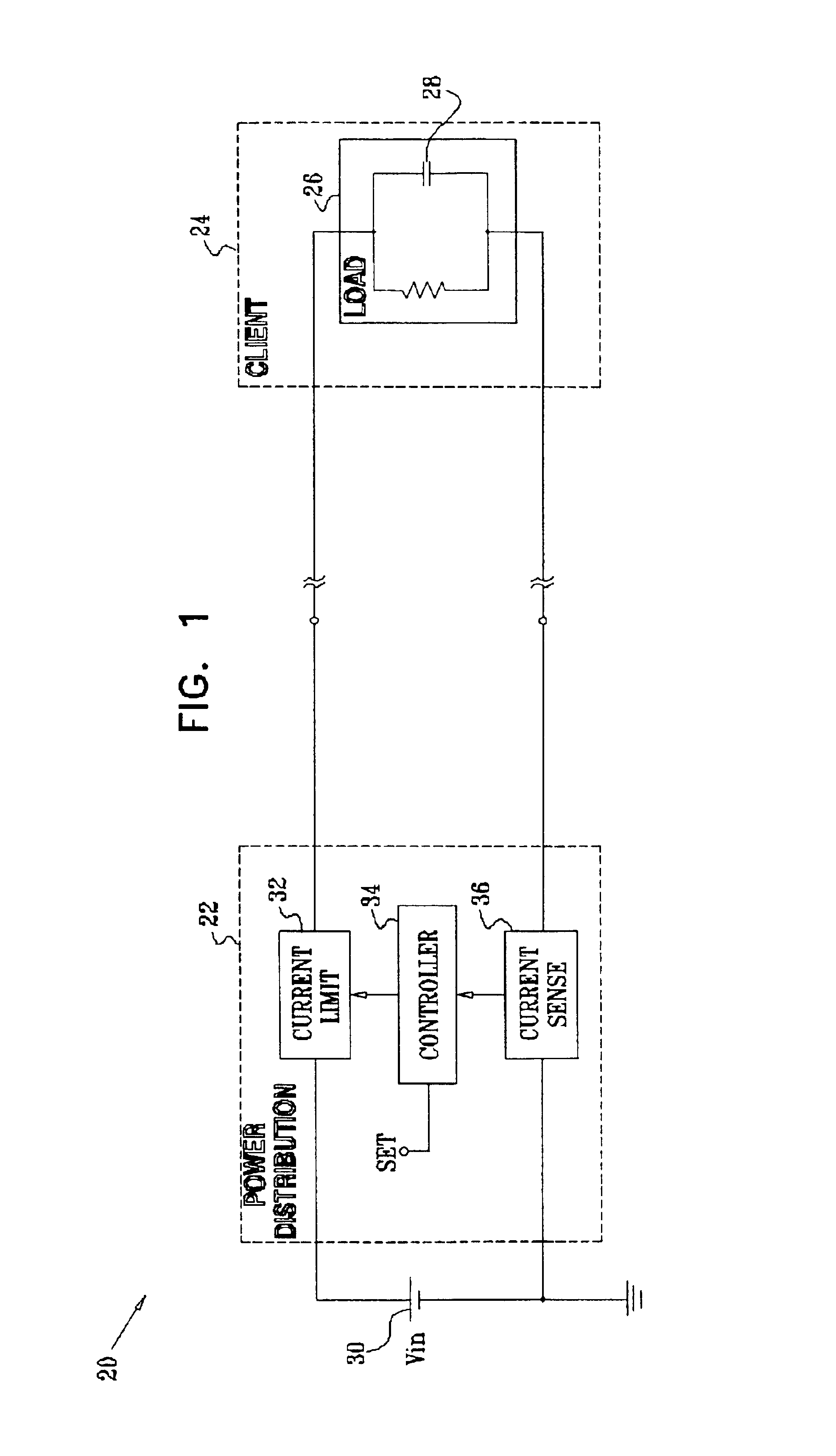
FIG. 1 is a block diagram that schematically illustrates a power supply system 20 with digital current control, in accordance with a preferred embodiment of the present invention. For the sake of simplicity, system 20 is shown as comprising a master power distribution unit 22, which provides DC power to a single client 24. In practical applications, particularly in the context of Power over LAN systems, master power distribution unit 22 may serve as a power hub, to provide power to multiple clients, such as Ethernet terminal devices receiving power from the hub over a LAN. Unit 22 may be integrated with the LAN in either a mid-span or an end-span configuration (as shown below in FIGS. 6A and 6B). Some aspects of the present invention are applicable both to such multi-client environments and to power supplies that drive a single load, as shown in FIG. 1. Other aspects of the present invention, described with reference to certain of the figures that follow, provide solutions that are ...


PUM


Abstract

Power distribution apparatus, for controlling supply of a current from an electrical power source to at least one load, includes a current sensor, which is coupled to provide an indication of a magnitude of the current flowing to the at least one load. A current limiter is adapted, responsive to the indication, to apply a pulse width modulation to the current drawn from the source so as to maintain the magnitude of the current flowing to the at least one load within a predetermined limit.

Description

FIELD OF THE INVENTIONThe present invention relates generally to power supplies, and specifically to methods and circuitry for avoiding current overload in the use of such power supplies.BACKGROUND OF THE INVENTIONPower over LAN™ is a new technology that enables DC power to be supplied to Ethernet data terminals over ordinary Category 5 cabling. This technology enables the terminals to receive their operating power over the same Ethernet local area network (LAN) that they use for data communication. It thus eliminates the need to connect each terminal to an AC power socket, and to provide each terminal with its own AC / DC power converter. Further aspects of this technology are described in PowerDsine Application Note 115, entitled “Power over LAN™: Building Power Ready Devices” (PowerDsine Ltd., Hod Hasharon, Israel), which is incorporated herein by reference. The LAN MAN Standards Committee of the IEEE Computer Society is developing specifications for Power over LAN systems, as desc...

Claims


Application Information

Patent Timeline
Patent Type & Authority Patents(United States)
IPC IPC(8): H02M3/158H02M3/157H02M3/04H02J1/04H02M1/00H02M1/14H02M1/42
CPCH02H9/001H02J1/04H02M1/143H02M1/4208H02M1/4258H02M3/1584H02M3/157Y02B70/126H02M2001/008H02M2001/0093H02M2003/1557H02M1/008H02M1/0093H02M3/1557Y02B70/10Y02P80/10
Inventor BERSON, YUVALFERENTZ, ALONKORCHARZ, DRORBARNEA, NADAVELKAYAM, SHIMONPINCU, DAVID
Owner CISCO TECH INC
Why Eureka
Try Eureka