Decreasing spin up time in a disk drive by adjusting a duty cycle of a spindle motor PWM signal to maintain constant average input current

a technology of a spindle motor and a duty cycle, which is applied in the direction of motor/generator/converter stopper, electric controller, dynamo-electric converter control, etc., can solve the problems of increased spin up time, and increased head wear in the disk driv

Inactive Publication Date: 2005-11-22
WESTERN DIGITAL TECH INC
View PDF22 Cites 122 Cited by
  • Summary
  • Abstract
  • Description
  • Claims
  • Application Information

AI Technical Summary

Benefits of technology

[0016]In yet another embodiment, a voltage sensor generates a voltage sense signal representing a voltage level of the supply voltage. The spindle driver is responsive to the first current sense signal to control the amount of current drawn by the windings from the supply voltage during a spin up mode of the disk drive. The spindle driver is responsive to the voltage sense signal to control the amount of current drawn by the windings from the supply voltage during a steady state mode of the disk drive. In one embodiment, the duty cycle of the PWM signal is adjusted in response to the voltage sense signal.

Problems solved by technology

The supply voltage is periodically applied to the windings of the spindle motor in a desired commutation sequence resulting in a rotational torque.
However, to ensure the supply voltage current limitations are not exceeded prior art disk drives are typically designed so that during the spin up process the spindle motor draws as little as 60% of the available current from the supply voltage.
This increases the spin up time which is undesirable, particularly as the operating spin rate increases.
Further, the increased spin up time increases head wear in disk drives that park the head on a landing zone of the disk.
The capacitor must be large enough to store a sufficient amount of current to enable higher torque and faster spin up times. However, mounting a large, discrete capacitor on the printed circuit board assembly (PCBA) is undesirable.
In addition, there is an undesirable delay associated with charging the capacitor prior to initiating the spin up process.

Method used


Image

  • Decreasing spin up time in a disk drive by adjusting a duty cycle of a spindle motor PWM signal to maintain constant average input current
  • Decreasing spin up time in a disk drive by adjusting a duty cycle of a spindle motor PWM signal to maintain constant average input current
  • Decreasing spin up time in a disk drive by adjusting a duty cycle of a spindle motor PWM signal to maintain constant average input current

Examples


Embodiment Construction

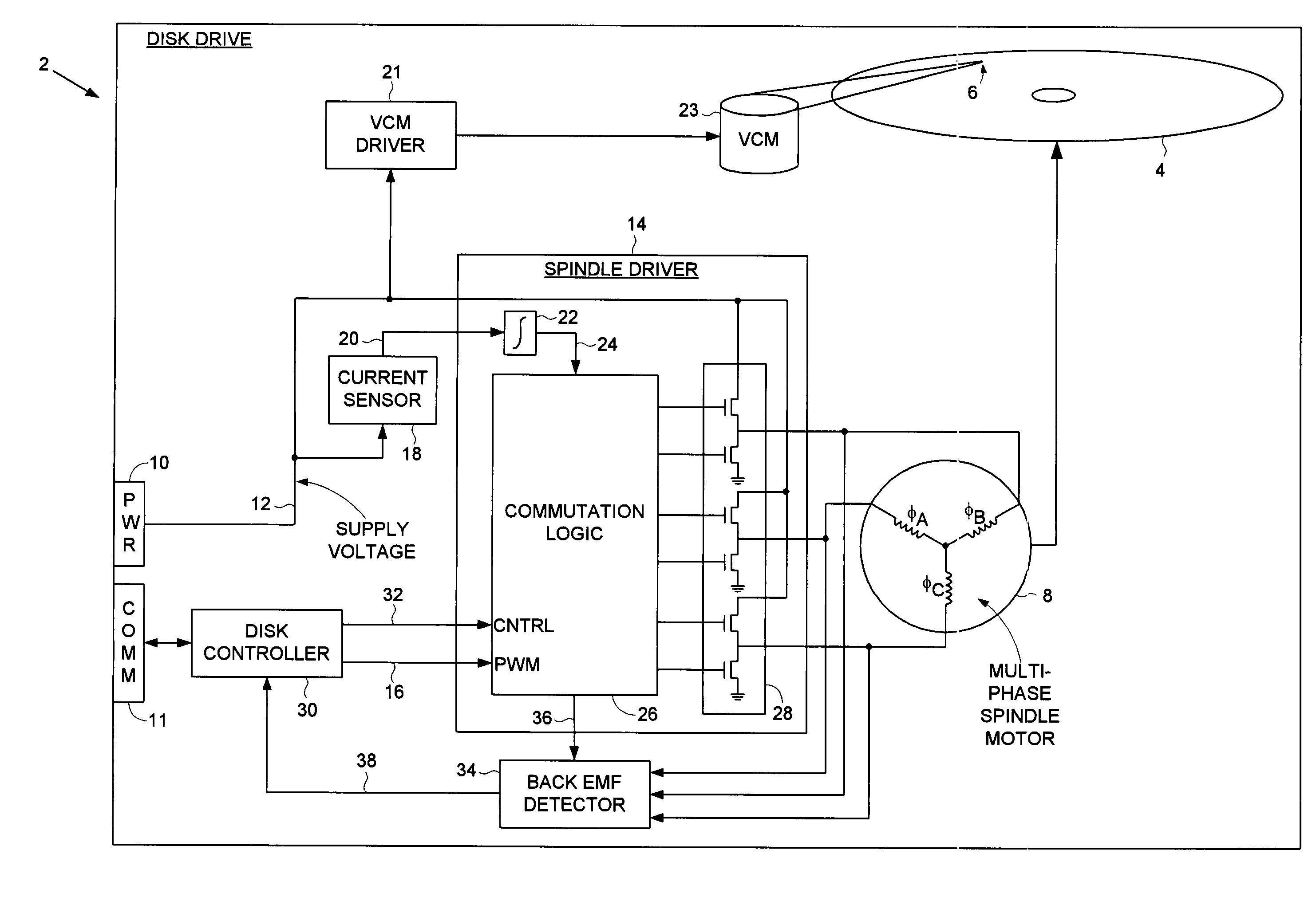
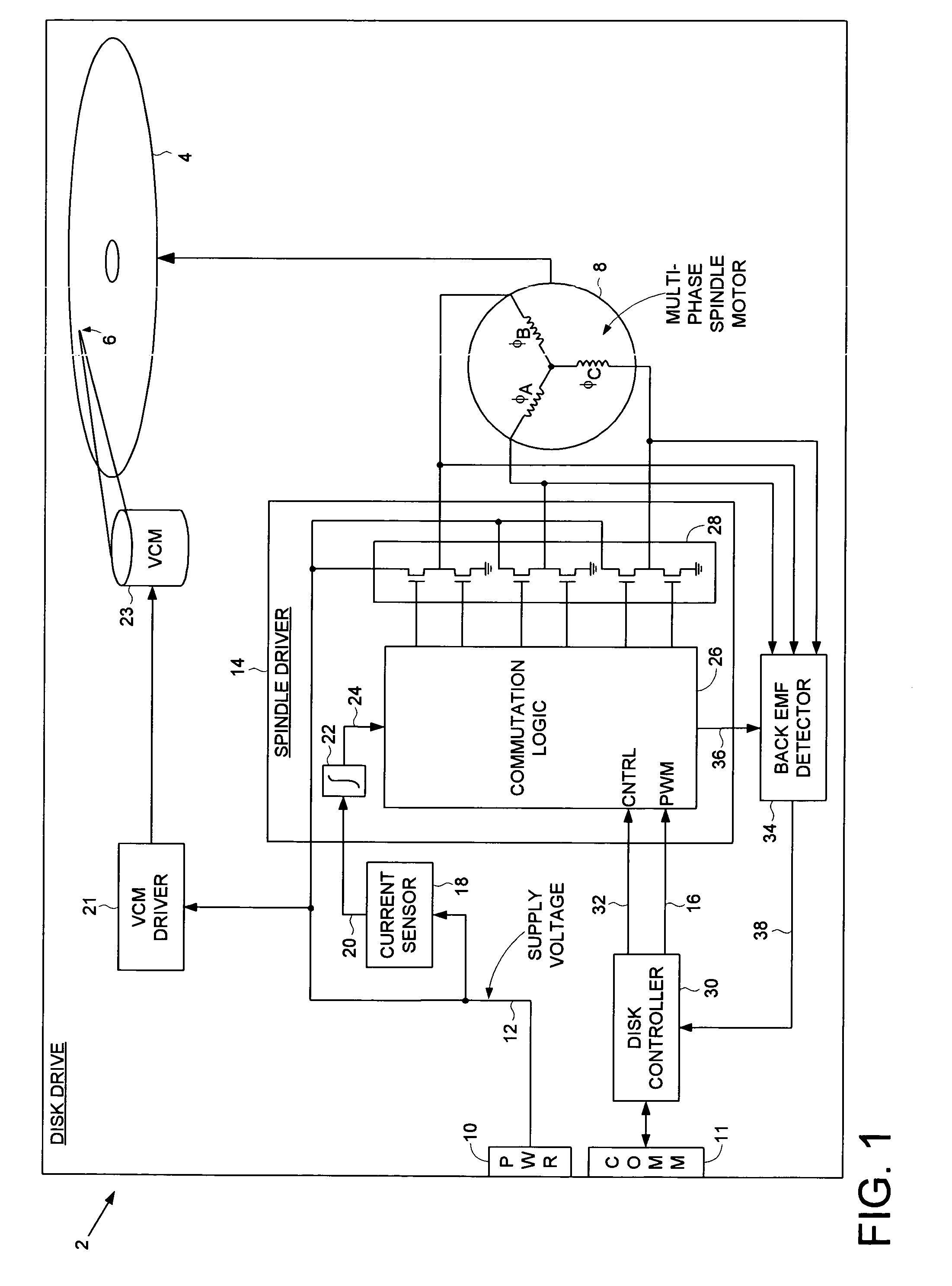
[0033]FIG. 1 shows a disk drive 2 connectable to a host computer according to an embodiment of the present invention. The disk drive 2 comprising a disk 4, a head 6 actuated radially over the disk 4, and a spindle motor 8 for rotating the disk 4, the spindle motor 8 comprising a plurality of windings (e.g., φA, φB, φC). The disk drive 2 further comprises an interface 10 for receiving a supply voltage 12 from the host computer. A spindle drive 14 applies a current from the supply voltage 12 to the windings of the spindle motor 8 in response to a pulse width modulated (PWM) signal 16. A first current sensor 18 generates a first current sense signal 20 representing a current flowing from the supply voltage 12. An integrator 22 integrates the first current sense signal 20 to generate an integration signal 24, wherein a duty cycle of the PWM signal 16 is adjusted in response to the integration signal 24.

[0034]In the embodiment of FIG. 1, the supply voltage 12 is applied to a VCM driver 2...


PUM

PropertyMeasurementUnit
supply voltageaaaaaaaaaa
currentaaaaaaaaaa
current senseaaaaaaaaaa

Abstract

A disk drive is disclosed comprising a spindle motor for rotating a disk, wherein the current applied to the spindle motor is controlled by adjusting a duty cycle of a pulse width modulated (PWM) signal. A current sensor generates a current sense signal representing a current flowing from a supply voltage. The current sense signal is integrated to generate an integration signal. The integration signal is compared to a threshold, and the result of the comparison is used to adjust the duty cycle of the PWM signal. In this manner the disk drive draws essentially constant average input current from the supply voltage which decreases the spin up time of the disk.

Description

CROSS REFERENCE TO RELATED APPLICATIONS AND PATENTS[0001]This application is related to U.S. Pat. No. 5,898,283 entitled “VOLTAGE FEEDFORWARD CONTROL SYSTEM FOR A SPINDLE MOTOR OF A DISK DRIVE” issued on Apr. 27, 1999, the disclosures of which is incorporated herein by reference.BACKGROUND OF THE INVENTION[0002]1. Field of the Invention[0003]The present invention relates to disk drives for computer systems. More particularly, the present invention relates to decreasing a spin up time for a disk drive by adjusting a duty cycle of a spindle motor PWM signal to maintain constant average input current.[0004]2. Description of the Prior Art[0005]The spindle motor of a disk drive is typically driven by a supply voltage provided by a host computer. The supply voltage is periodically applied to the windings of the spindle motor in a desired commutation sequence resulting in a rotational torque. During each commutation sequence, a selected winding is connected to the supply voltage through a ...

Claims


Application Information

Patent Timeline
Patent Type & Authority Patents(United States)
IPC IPC(8): G05B11/28G05B11/01G11B19/20
CPCG05B11/28G11B19/20
Inventor BENNETT, GEORGE J.RYAN, ROBERT P.
Owner WESTERN DIGITAL TECH INC
Why Eureka
Try Eureka