Arrangements for a current sensing circuit and integrated current sensor

a current sensing circuit and integrated current sensor technology, applied in the field of current sensing circuits, can solve problems such as reducing breakdown voltag

Active Publication Date: 2010-10-19
ALLEGRO MICROSYSTEMS INC
View PDF168 Cites 122 Cited by
  • Summary
  • Abstract
  • Description
  • Claims
  • Application Information

AI Technical Summary

Problems solved by technology

However, close proximity tends to reduce the breakdown voltage.

Method used


Image

  • Arrangements for a current sensing circuit and integrated current sensor
  • Arrangements for a current sensing circuit and integrated current sensor
  • Arrangements for a current sensing circuit and integrated current sensor

Examples


Embodiment Construction

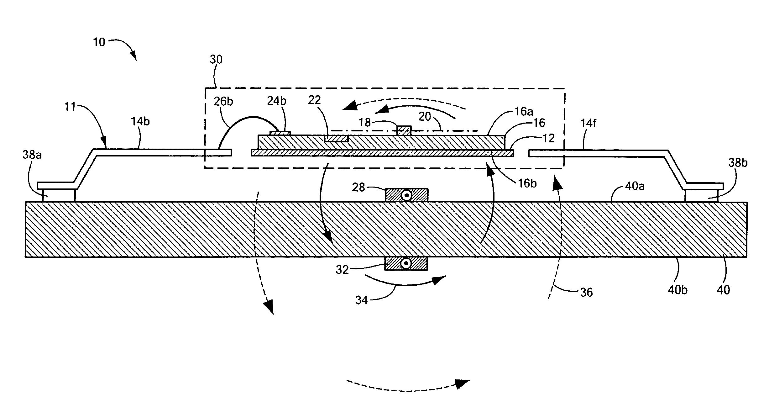
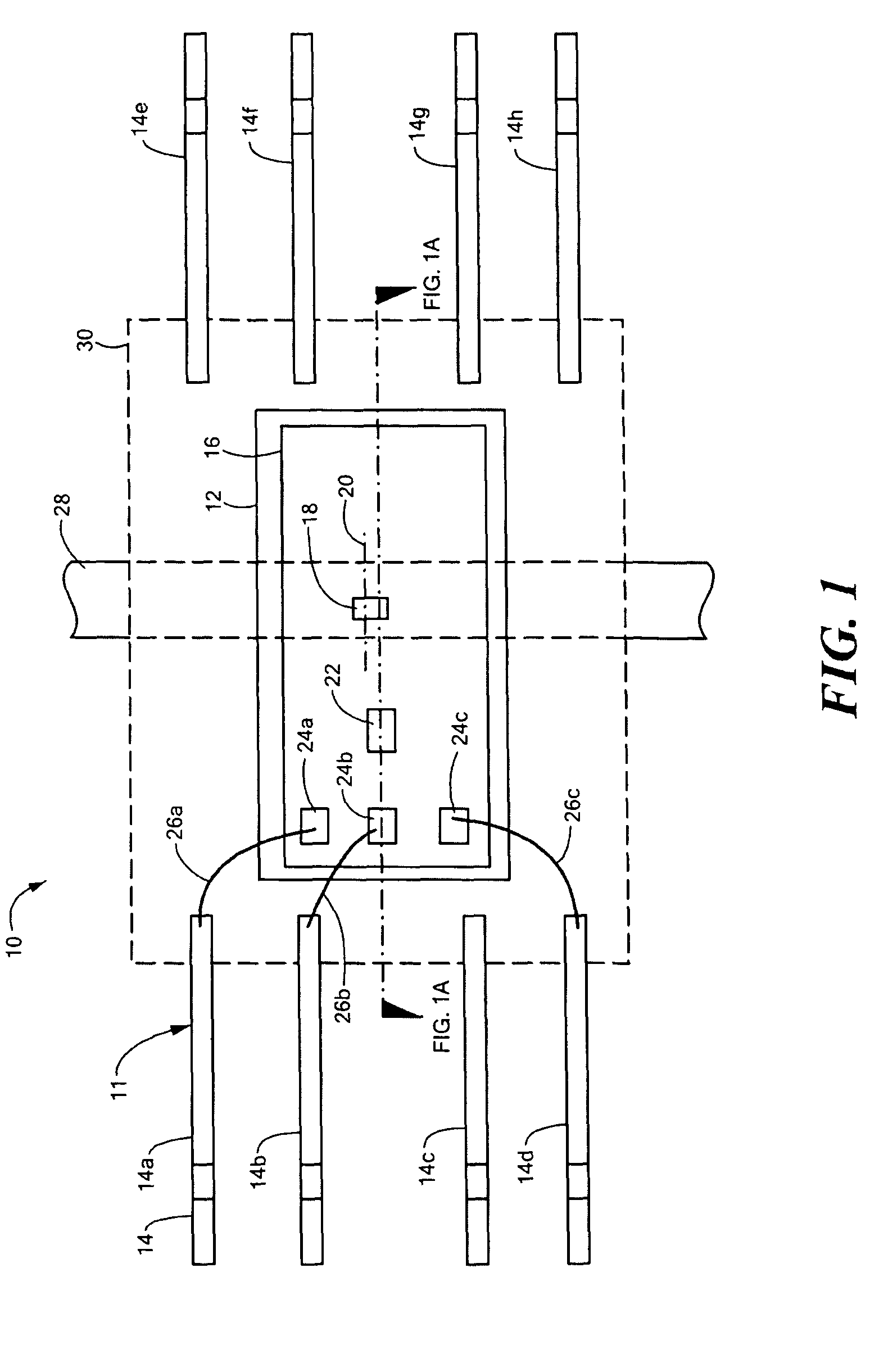
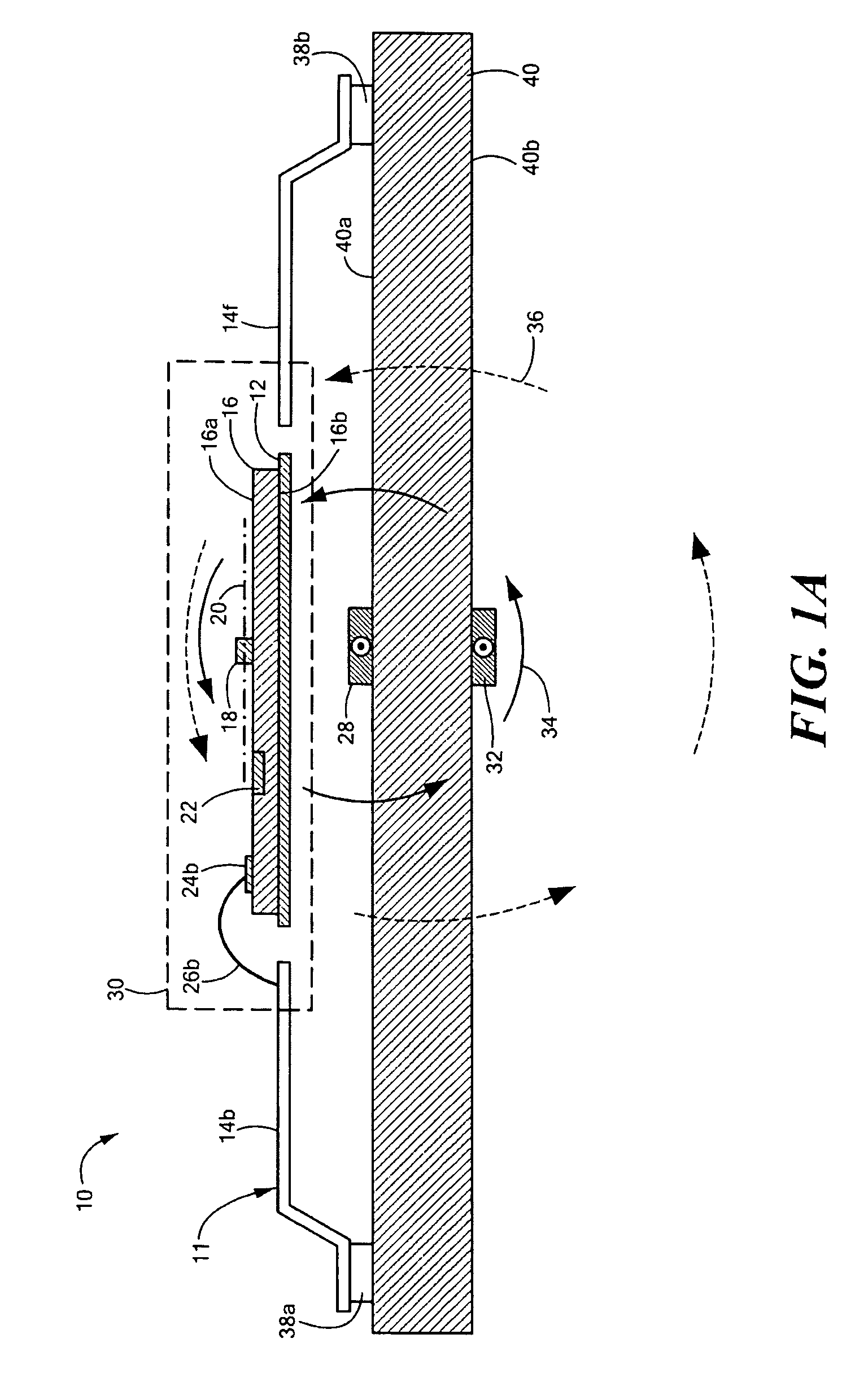
[0028]Before describing the present invention, some introductory concepts and terminology are explained. As used herein, the term “magnetic field sensing element” is used to describe an electronic component that is responsive to and can be used to measure magnetic fields. The magnetic field sensing element can be of a type including, but not limited to, a Hall effect element and a magnetoresistance element. The Hall effect element can be a horizontal type or a vertical type. The magnetoresistance element can be of a type including, but not limited to, a giant magnetoresistance (GMR) element, an anisotropic magnetoresistance (AMR) element, a magnetic tunnel junction (MJT) element, and a tunneling magnetoresistance (TMR) element.

[0029]As used herein, the term “magnetic field sensor” is used to describe an electronic circuit, which includes a magnetic field sensing element, and which is responsive to and can be used to measure a magnetic field. As used herein, the term “current sensor”...


PUM


Abstract

An electronic circuit for sensing a current includes a circuit board having first and second major opposing surfaces and a current conductor for carrying the current. The current conductor includes a circuit trace disposed upon the circuit board. The electronic circuit also includes an integrated circuit disposed upon and electrically coupled to the circuit board at a position so as to straddle the current conductor.

Description

CROSS REFERENCE TO RELATED APPLICATIONS[0001]Not Applicable.STATEMENT REGARDING FEDERALLY SPONSORED RESEARCH[0002]Not Applicable.FIELD OF THE INVENTION[0003]This invention relates generally to current sensing circuits and, more particularly, to current sensing circuits having respective integrated current sensors.BACKGROUND OF THE INVENTION[0004]As is known in the art, one type of conventional current sensor uses a Hall effect element, which generates a voltage in response to a magnetic field associated with a current passing through a conductor. Typical current sensors of this type include a Hall effect element mounted on a dielectric material, for example a circuit board. In some applications, a ferrous core (magnetic flux concentrator) is used in proximity to the Hall effect element.[0005]Another type of current sensor uses a magnetoresistance element, which changes resistance in response to a magnetic field associated with a current passing through a conductor. A fixed electrica...

Claims


Application Information

Patent Timeline
Patent Type & Authority Patents(United States)
IPC IPC(8): G01R15/20
CPCG01R15/202G01R15/207G01R15/205H01L2924/181H01L2224/05553H01L2224/16145H01L2224/32145H01L2224/48137H01L2224/48145H01L2224/48247H01L2224/49171H01L2224/73265H01L2924/00012H01L2924/00
Inventor DOOGUE, MICHAEL C.DICKINSON, RICHARDTAYLOR, WILLIAM P.
Owner ALLEGRO MICROSYSTEMS INC
Why Eureka
Try Eureka