Eureka AIR delivers breakthrough ideas for toughest innovation challenges, trusted by R&D personnel around the world.

Coil core patting and aligning device

A technology for a snapping device and a core, which is applied to the field of a core snapping device, can solve the problems of coiling affecting transportation and hoisting, inability to beat the steel coil, and the height of the collision plate is not adjustable, and achieves significant beneficial effects and scope of application. Wide range of effects suitable for application and promotion

Inactive Publication Date: 2016-11-09
BINZHOU UNIV
View PDF12 Cites 3 Cited by
  • Summary
  • Abstract
  • Description
  • Claims
  • Application Information

AI Technical Summary

Problems solved by technology

The patent number is CN201410114877.3, and the patent document of the invention name is a device and a control method for aligning steel coil towers. It discloses a device for aligning steel coils. One end of the steel coil can be aligned, while the other end is blocked by the baffle plate to achieve the alignment of the steel coil. In the actual use process, the baffle plate only has a blocking effect and does not have a continuous beating effect. , so that the alignment effect of the baffle is not good
Moreover, since the height of the striking plate is not adjustable, it cannot beat steel coils with different diameters.
[0003] The quality of coiling not only affects the transportation and lifting, but also affects the processing and use of the next process

Method used


Image

  • Coil core patting and aligning device
  • Coil core patting and aligning device
  • Coil core patting and aligning device

Examples


Embodiment Construction

[0019] The present invention will be further described below in conjunction with the accompanying drawings and embodiments.

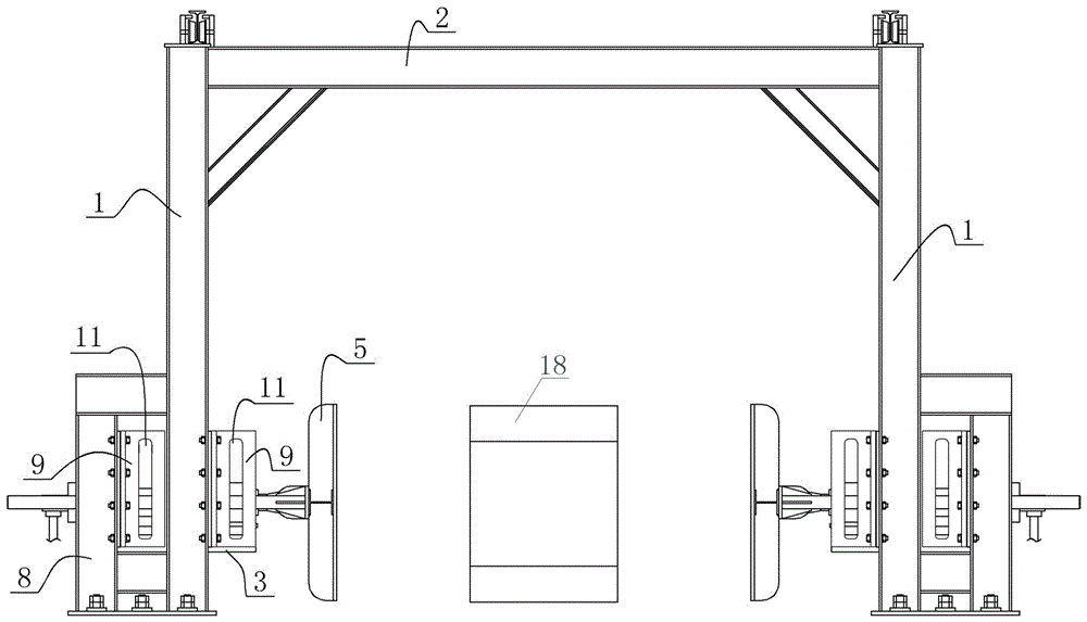
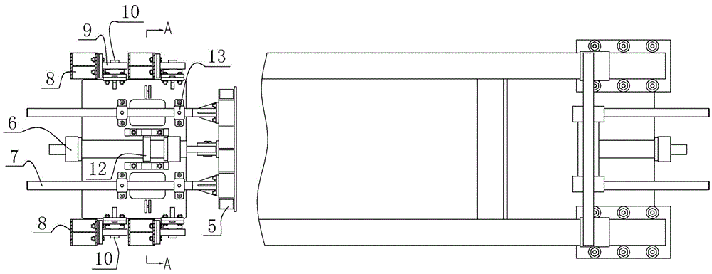
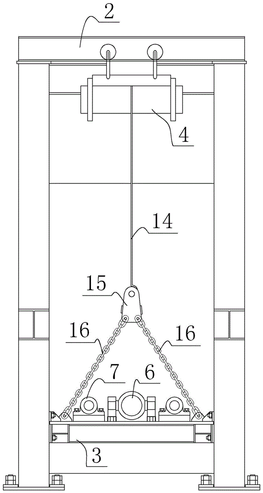
[0020] Such as figure 1 , figure 2 and image 3 As shown, the front view, top view and left side view of the winding core alignment device of the present invention are provided respectively, and the winding core alignment device of the present invention shown in the figure is composed of a vertical beam 1, a cross beam 2, an elevating platform 3, and a driving motor 4 , clapping hands 5, hydraulic cylinder 6, guide rod 7, guide rail 9, steel wire rope 14, connecting plate 15, chain 16, vertical beam 1 and cross beam 2 form the frame, and the left and right sides are provided with two vertical beams 1, The crossbeam 2 is fixed on the top of the vertical beam 1, and the left and right sides of the frame are all provided with an elevating type clapping mechanism, and the elevating type clapping mechanism is composed of a lifting table 3, a driving motor...


PUM


Abstract

The invention discloses a coil core patting and aligning device. The coil core patting and aligning device comprises a frame and a lifting type patting and aligning mechanism, wherein the frame comprises vertical beams and a transverse beam. The coil core patting and aligning device is characterized in that the lifting type patting and aligning mechanism comprises lifting platforms, driving motors, patting palms and hydraulic cylinders; the driving motors drive the lifting platforms to rise and fall; the hydraulic cylinders are horizontally fixed on the lifting platforms; the patting palms face to the inner side of the frame; inner end surfaces of the patting palms are steel coil patting and aligning planes; the outer end surfaces of the patting palms are fixed to piston rods of the hydraulic cylinders; guide rods arranged in the same direction of each hydraulic cylinder are fixed on two sides of each hydraulic cylinder; the ends of the guide rods are fixed to the outer end surfaces of the patting palms. The coil core patting and aligning device is capable of patting coil core positions on two sides of the steel coils under the driving action of the hydraulic cylinders on the patting palms and patting and aligning the coil cores; the coil core patting and aligning device is suitable for patting and aligning different-sized steel coils by driving the lifting platforms to rise and fall; the range of application is more extensive; the beneficial effects are remarkable; the coil core patting and aligning device is suitable for popularization and application.

Description

technical field [0001] The invention relates to a winding core aligning device, more specifically, to a winding core aligning device for beating the tower-shaped end face of the core of a hot-rolled steel coil. Background technique [0002] The curly tower shape refers to the phenomenon that the end faces of both sides of the curled formed steel coil are partially overflowed and the whole is uneven, and it is a quality defect in the production process of hot-rolled strip steel. The generation of the coiling tower has a great impact on the product qualification rate, economic benefits and social benefits of the steel mill. In the face of fierce market competition and increasingly high demands from customers, coiling has become a quality indicator in the production process. The patent number is CN201410114877.3, and the patent document of the invention name is a device and a control method for aligning steel coil towers. It discloses a device for aligning steel coils. One en...

Claims


Application Information

Patent Timeline
IPC IPC(8): B21C47/26
CPCB21C47/26
Inventor 章健荀玉伟邓立君
Owner BINZHOU UNIV
Why Eureka
Eureka Blog
Learn More