Pouring flow inoculation feeding device

A technology of feeding device and inoculation with flow, which is applied in the field of non-hand-held pouring inoculation feeding device with flow, can solve the problems of difficult quantitative and uniform control of feeding amount, high labor intensity of operators, and spheroidization decline in pouring time, and achieves relative position Reliable, simple structure, universal and practical effect

Active Publication Date: 2018-02-16
CHANGZHOU LANGRUI CASTING +1
View PDF8 Cites 2 Cited by
  • Summary
  • Abstract
  • Description
  • Claims
  • Application Information

AI Technical Summary

Problems solved by technology

Manually put a shelf on the sand box, and place a funnel containing a certain amount of inoculant on the shelf to incubate with the flow. This method requires special inoculation operators with flow, and the labor intensity of the operators is high.
There are also hanging funnels on the ladle nozzle for inoculation with the flow. Most of this method cannot ensure that the funnel can always be kept above the molten iron for inoculation during the process of different inclination angles of the ladle, and it is difficult to quantitatively and uniformly control the amount of addition, especially for the same product. Hand-held operation for a long time in the process of pouring in large quantities will cause a great test to the physical strength and energy of the incubating workers, and prolonging the pouring time will easily lead to spheroidization decline
The utility model with the Chinese patent application number 201020247336.5 discloses a flow inoculation device used on a hand-cast ladle, including a funnel assembly and a support frame assembly. However, when the ladle has a short spout or is not a teapot spout, the above utility model cannot keep the spout of the flow-following inoculation funnel above the cast iron flow. When the ladle is tilted to a certain angle, the inoculation funnel The inoculant will deviate from the molten iron flow

Method used


Image

  • Pouring flow inoculation feeding device
  • Pouring flow inoculation feeding device
  • Pouring flow inoculation feeding device

Examples


Embodiment 1

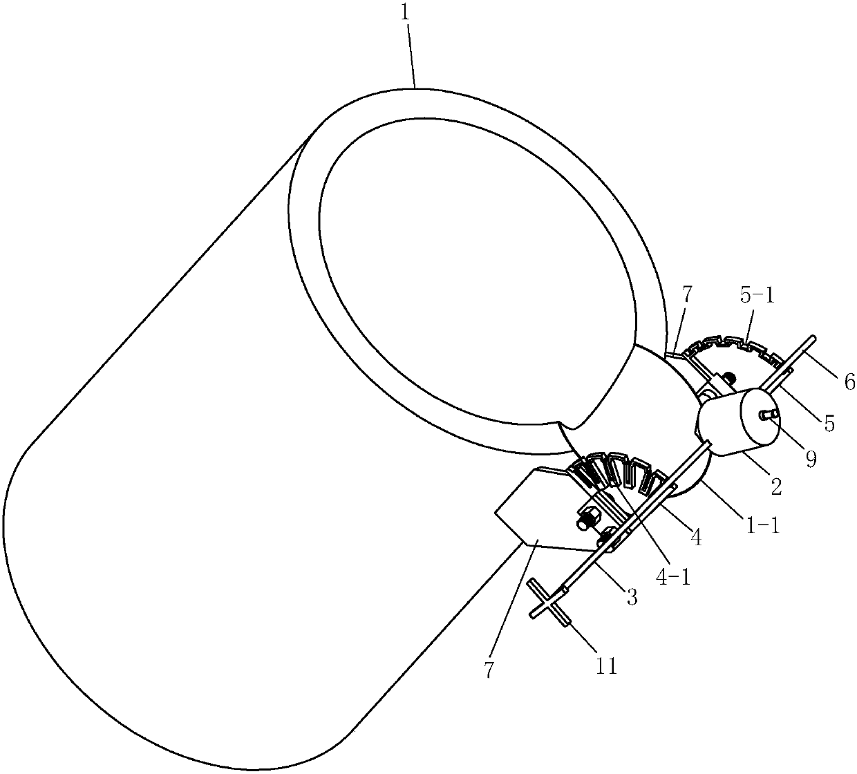
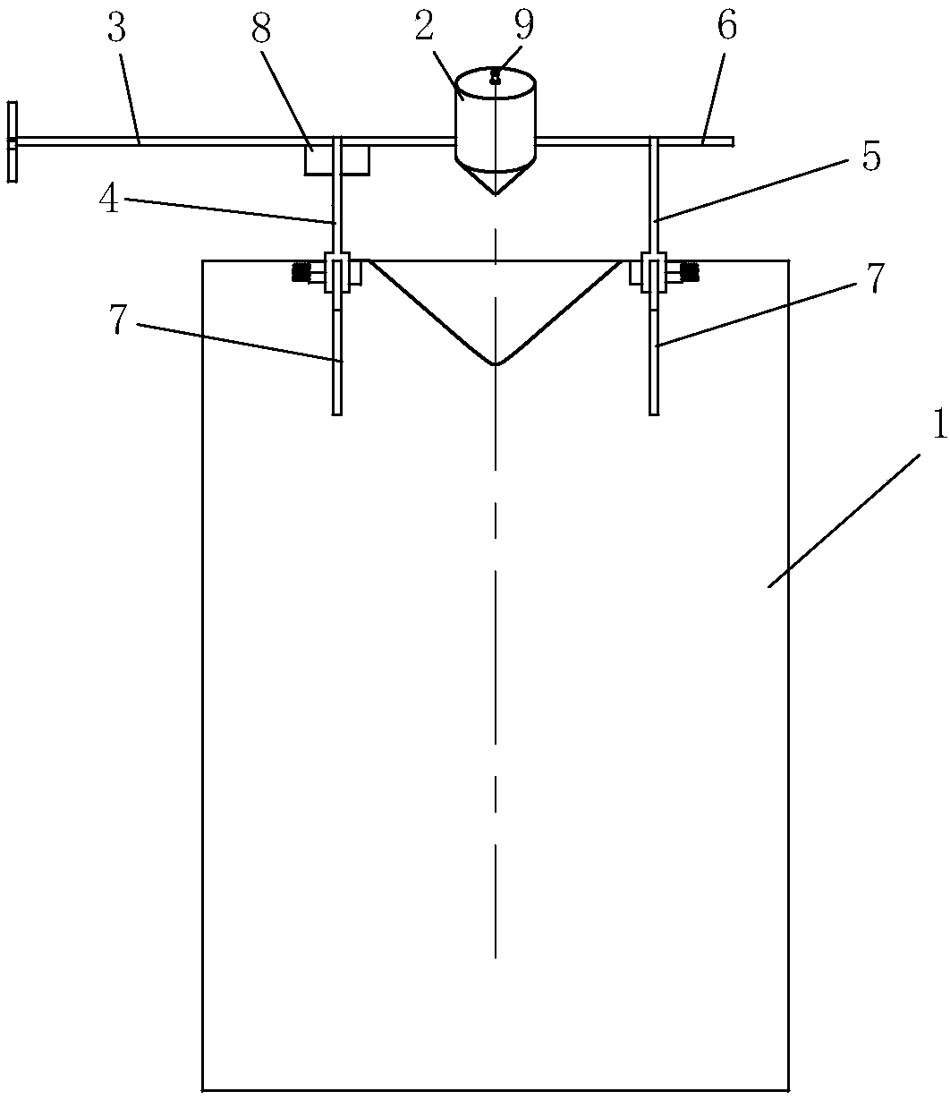
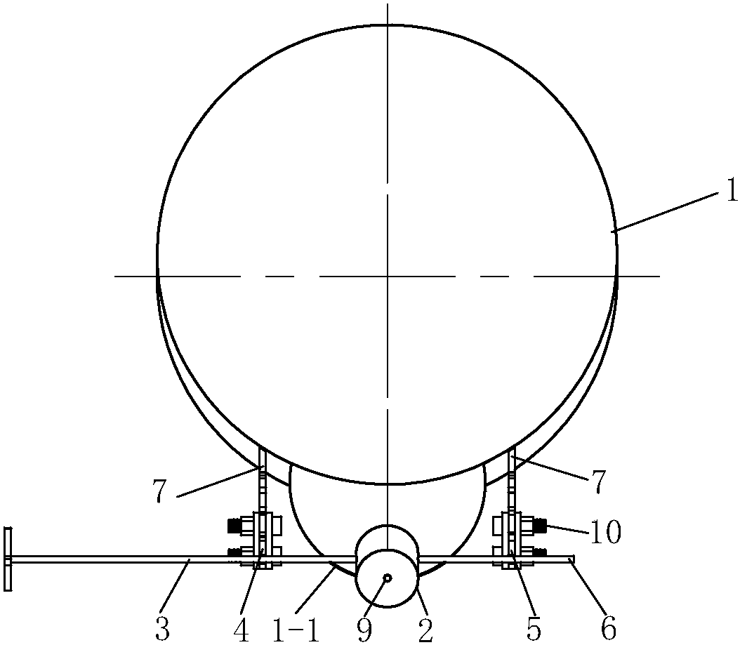
[0017] See Figure 1 to Figure 7 , the present embodiment has a ladle 1 and a hopper 2 for storing the inoculant, the two sides of the hopper 2 are respectively fixed with a first support rod 3 and a second support rod 6 with the same diameter, and the first support rod 3 and the second support rod 6 On the same center line, and the center line passes below the center of gravity of the hopper 2. A handle 11 is provided on the end of the first support rod 3 . The lower part of the hopper 2 is a cone, the top of which has a feed port, the feed port is provided with a screw-connected plug 9, and the bottom of the hopper 2 has a discharge port 2-1.

[0018] The outer wall of the ladle 1 and the parts on both sides of the ladle mouth 1-1 are welded with support plates 7, and the two support plates 7 are respectively connected by bolts 10 to a first fan-shaped groove plate 4 and a second fan-shaped groove plate 5. The positions of the first fan-shaped slot plate 4 and the second ...


PUM


Abstract

A pouring stream inoculation charging device is provided with a casting ladle and a hopper storing an inoculation agent. A first supporting rod and a second supporting rod which share the same center line are fixed to the two sides of the hopper correspondingly. A charging opening is formed in the top of the hopper, and a plug is arranged in the charging opening. A discharging opening is formed in the bottom of the hopper. Supporting plates are fixed to the portion, on the two sides of the casting ladle, of the outer wall of the casting ladle correspondingly. A first fan-shaped trough plate and a second fan-shaped trough plate which are symmetrical in position are connected to the two supporting plates correspondingly. The first fan-shaped trough plate and the second fan-shaped trough plate are each provided with a plurality of radial grooves, the first supporting rod is placed in the corresponding radial grooves of the first fan-shaped trough plate, and the second supporting rod is placed in the corresponding radial grooves of the second fan-shaped trough plate. The first supporting rod is provided with insertion plates matched with the radial grooves of the first fan-shaped trough plate, and the insertion plates are inserted in the radial grooves of the first fan-shaped trough plate. By means of the pouring stream inoculation charging device, unintermittent manual operation is not needed in the pouring process, the angle of inclination of the hopper can be adjusted, and the inoculation treatment can be carried out on molten iron accurately and uniformly.

Description

technical field [0001] The invention relates to a non-hand-held pouring and flowing inoculation feeding device. Background technique [0002] In the production process of cast iron, the inoculation process is an indispensable process in the production process of modern cast iron. How to add less inoculant to the molten iron to change the solidification process of the molten iron, improve the as-cast structure, and improve the mechanical properties and processing performance , the inoculation process is very important. As far as ductile iron is concerned, inoculation can increase the tendency of graphite spheres to precipitate, and obtain evenly distributed, fine-grained graphite. Especially for the production of as-cast ductile iron, special attention should be paid to inoculation treatment. After selecting the inoculant variety, the addition method of the inoculant becomes the key. In the inoculation process, inoculation with flow is more difficult to control. At present...

Claims


Application Information

Patent Timeline
Patent Type & Authority Patents(China)
IPC IPC(8): B22D1/00
CPCB22D1/00
Inventor 喻光远朱正锋刘宇沈兵伍
Owner CHANGZHOU LANGRUI CASTING
Why Eureka
Try Eureka