In-mould assembling and welding structure

A technology of welding structure and in-mold assembly, which is applied in the field of injection molds, can solve the problems of high production cost and long process chain, and achieve the effect of shortening the process chain and reducing the ultrasonic post-treatment process

Inactive Publication Date: 2016-11-09
鸿利达模具科技(中山)有限公司
View PDF3 Cites 4 Cited by
  • Summary
  • Abstract
  • Description
  • Claims
  • Application Information

AI Technical Summary

Problems solved by technology

[0002] Under normal circumstances, the injection molding industry will make a single set of molds for a single product, produce the product, then assemble the product, and then weld the product together with ultrasonic technology; such as the gas-liquid flow monitor designed and produced by our company, the The product consists of three parts, so the traditional design will design three molds, and the parts will be produced separately. After the parts are produced, the three parts will be assembled into the whole gas-liquid flow monitor. The disadvantage of this design is: it needs to be done 3 sets of molds to produce products; post-processing assembly and ultrasonic welding are also required
This design results in a long process chain for production and high production costs

Method used


Image

  • In-mould assembling and welding structure
  • In-mould assembling and welding structure
  • In-mould assembling and welding structure

Examples


Embodiment Construction

[0016] The specific implementation manners of the present invention will be further described in detail below in conjunction with the accompanying drawings. The following embodiments are used to illustrate the present invention, but not to limit the scope of the present invention.

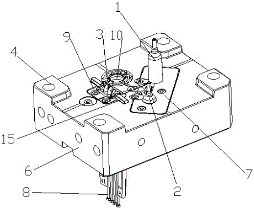
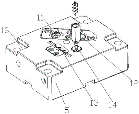
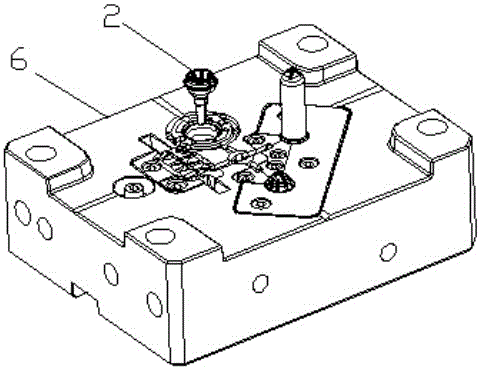
[0017] like figure 1 , 2 , 3, 4, and 5, the in-mold assembly and welding structure of the present invention includes a front mold core 5, a rear mold core 6, a push plate 7 and a rear mold insert 9 that are movably arranged on the upper surface of the rear mold core 6, The upper cover core 2 for the upper cover of the injection-molded gas-liquid flow monitor, the main body core 1 for the main body of the injection-molded gas-liquid flow monitor, which are arranged on the push plate 7, and the rear mold insert 9 is provided with a The lower molding cavity 3 of the blade of the gas-liquid flow monitor; the lower assembly cavity 10 is arranged on the rear mold core, and the lower assembly cavity 10 ...


PUM


Abstract

The invention discloses an in-mould assembling and welding structure. The in-mould assembly and welding structure comprises a front mould core, a rear mould core, a pushing plate and a rear mould insert which are movably arranged on the upper surface of the rear mould core, an upper cover mould core which is arranged on the pushing plate for injection-molding an upper cover of a gas-liquid flow monitor and a main body mould core used for injection-molding a main body of the gas-liquid flow monitor; the rear mould insert is equipped with a lower forming cavity used for injection-molding a blade of the gas-liquid flow monitor; a lower assembly cavity is formed in the rear mould core; the lower assembly cavity is positioned at one side of the pushing plate and the rear mould insert; the front mould core is provided with a main body mould cavity used for injection-molding the main body of the gas-liquid flow monitor, an upper cover mould cavity used for injection-molding the upper cover of the gas-liquid flow monitor, an upper forming cavity used for injection-molding the blade of the gas-liquid flow monitor, and an upper assembly cavity used for assembling; the main body mould cavity, the upper cover mould cavity, the upper forming cavity and the upper assembly cavity correspond to the main body mould core, the upper cover mould core, the lower forming cavity and the lower assembly cavity respectively; and ejector pins are arranged underneath the rear mould core.

Description

technical field [0001] The invention relates to the technical field of injection molds, in particular to an in-mold assembly and welding structure. Background technique [0002] Under normal circumstances, the injection molding industry will make a single set of molds for a single product, produce the product, then assemble the product, and then weld the product together with ultrasonic technology; such as the gas-liquid flow monitor designed and produced by our company, the The product consists of three parts, so the traditional design will design three molds, and the parts will be produced separately. After the parts are produced, the three parts will be assembled into the whole gas-liquid flow monitor. The disadvantage of this design is: it needs to be done 3 sets of molds to produce products; post-processing assembly and ultrasonic welding are also required. This design results in a long process chain for production and high production costs. Contents of the invention...

Claims


Application Information

Patent Timeline
Patent Type & Authority Applications(China)
IPC IPC(8): B29C45/26
CPCB29C45/2602B29C45/0062B29C2045/0072
Inventor 吴学如冯中兵柳景荣
Owner 鸿利达模具科技(中山)有限公司
Why Eureka
Try Eureka