Steel box girder section design with anti-explosion and anti-impact effects

An explosion impact, steel box girder technology, applied in bridge construction, bridges, bridge parts, etc., can solve the problem of inability to guide the explosion-proof design of steel box girder, the force load and force mode are quite different, and no protection and optimization suggestions are proposed. and other problems, to achieve the effects of good compressive and tensile properties, expanding the force surface and slowing down the speed of failure

Inactive Publication Date: 2016-11-09
ZHONGBEI UNIV
View PDF6 Cites 11 Cited by
  • Summary
  • Abstract
  • Description
  • Claims
  • Application Information

AI Technical Summary

Problems solved by technology

[0003] Application number CN201210532410.1 proposes a method for anti-explosion damage of steel-concrete composite structures, which is mainly designed for steel castings and concrete castings separately, compared with steel box girder material selection, structural combination form, force load and force mode. Large, it is not yet possible to guide the explosion-proof design of steel box girders
The explosion of the steel box girder will have a severe local damage effect on the structure (Yao Shujian, Analysis of the local damage effect of the internal explosion of the car bomb steel box girder [J], Vibration and Shock, 2015(7):222-227.) (Geng Shaobo, Experimental study on the failure of steel box girder scale model under the action of blast shock wave [C], National Structural Engineering Academic Conference, 2016.), but no researchers have proposed protection and optimization suggestions on the design of steel box girder section

Method used


Image

  • Steel box girder section design with anti-explosion and anti-impact effects
  • Steel box girder section design with anti-explosion and anti-impact effects
  • Steel box girder section design with anti-explosion and anti-impact effects

Examples


Embodiment Construction

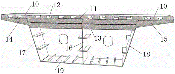
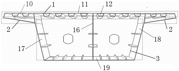
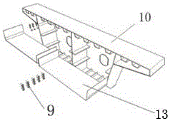
[0038] Such as Figure 1-Figure 5 As shown, a section design of a steel box girder anti-explosion impact, the steel box girder section 10 includes a roof 11, a U-shaped rib 12, a secondary roof 13, a longitudinal diaphragm 16, a first web 17, a second web 18, Bottom plate 19, along bridge type truss-foam aluminum composite member and cross bridge type truss-foam aluminum composite member;

[0039] The top plate 11 is arranged horizontally and a plurality of U-shaped ribs 12 are arranged at intervals on the bottom of the top plate 11, and the space between every two adjacent U-shaped ribs 12 of the plurality of U-shaped ribs 12 is set as the first explosion-proof shock zone 1 , the first explosion-proof shock zone 1 is filled with a single-layer bridge-type truss-foam aluminum composite member flush with the U-shaped rib 12;

[0040] A secondary top plate 13 is horizontally arranged below the top plate 11, the vertical distance between the secondary top plate 13 and the bottom...


PUM


Abstract

The invention relates to steel box girder section design with anti-explosion and anti-impact effects, belongs to the technical field of bridge engineering steel box girder structures, and aims at solving the technical problem that steel box girder section design of internally arranging an anti-explosion and anti-impact layer needs to be provided. According to the technical scheme, a top plate is horizontally arranged, multiple U-shaped ribs are arranged at the bottom of the top plate at intervals, and a space between every two adjacent U-shaped ribs serves as a first explosion-proof and impact-proof area which is filled with a single-layer along-bridge-type truss and foamed aluminum combined member flush with the corresponding U-shaped ribs; a secondary top plate is horizontally arranged below the top plate, the vertical distance between the secondary top plate and a bottom plate is not smaller than a half of the vertical distance between the top plate and the bottom plate, the thickness of the secondary plate is 1 / 4-1 / 2 of that of the top plate, and a space between the secondary top plate and the bottoms of the U-shaped ribs of the top plate serves as a third explosion-proof and impact-proof area which is filled with at least two layers of cross-bridge-type truss and foamed aluminum combined members in the vertical direction. The steel box girder section design with the anti-explosion and anti-impact effects is applied to roads and bridges.

Description

technical field [0001] The invention relates to a section design of a steel box girder anti-explosion impact, which belongs to the technical field of bridge engineering steel box girder structures. Background technique [0002] At present, the steel box girder structure is mainly used in urban elevated curved bridges, long-span cable-stayed bridges and suspension bridges. The overall calculation of the box girder structure mainly considers the dead load, vehicle load, wind load and earthquake load of the structure, and the explosion load has not been considered; When designing the cross-section of the beam structure, the overall stability of the structure during the construction process, local stability and fatigue problems during operation are mainly considered, and the problem of local impact has not been considered; the bridge deck, as the action surface of the vehicle load, is set on The top of the steel box girder is the main component of the structural stress optimizat...

Claims


Application Information

Patent Timeline
Patent Type & Authority Applications(China)
IPC IPC(8): E01D19/00E01D2/04E01D101/30
CPCE01D2/04E01D19/00E01D2101/30
Inventor 耿少波贺耀北吴增煜陈淑萍李建军靳小俊朱晋华程志王元龙张洪萍
Owner ZHONGBEI UNIV
Why Eureka
Try Eureka