Electromagnetic unlocking device

An unlocking device and electromagnetic technology, applied in the direction of building locks, non-mechanical transmission-operated locks, buildings, etc., can solve the problems of short working time of electromagnetic unlocking device and continuous power supply, and achieve the effect of avoiding continuous heating of the coil.

Active Publication Date: 2016-11-09
BEIJING MECHANICAL EQUIP INST
View PDF5 Cites 3 Cited by
  • Summary
  • Abstract
  • Description
  • Claims
  • Application Information

AI Technical Summary

Problems solved by technology

[0003] In view of the above analysis, the present invention aims to provide an electromagnetic unlocking device to solve the problem that the existing electromagnetic unlocking device needs to be continuously energized in order to maintain the unlocked state, resulting in continuous heating and short working hours of the electromagnetic unlocking device

Method used


Image

  • Electromagnetic unlocking device
  • Electromagnetic unlocking device
  • Electromagnetic unlocking device

Examples


Embodiment Construction

[0025] Preferred embodiments of the present invention will be specifically described below in conjunction with the accompanying drawings, wherein the accompanying drawings constitute a part of the application and are used together with the embodiments of the present invention to explain the principle of the present invention.

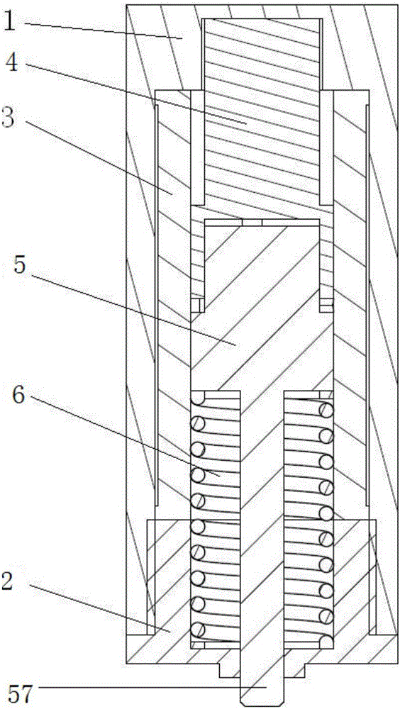
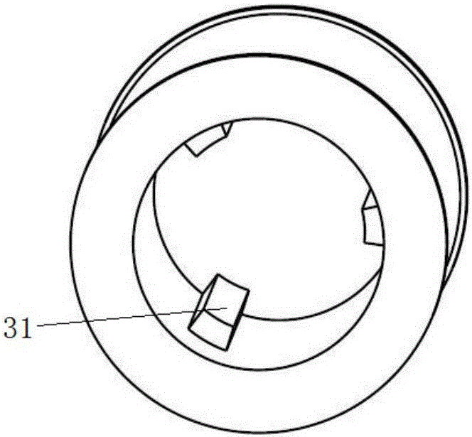
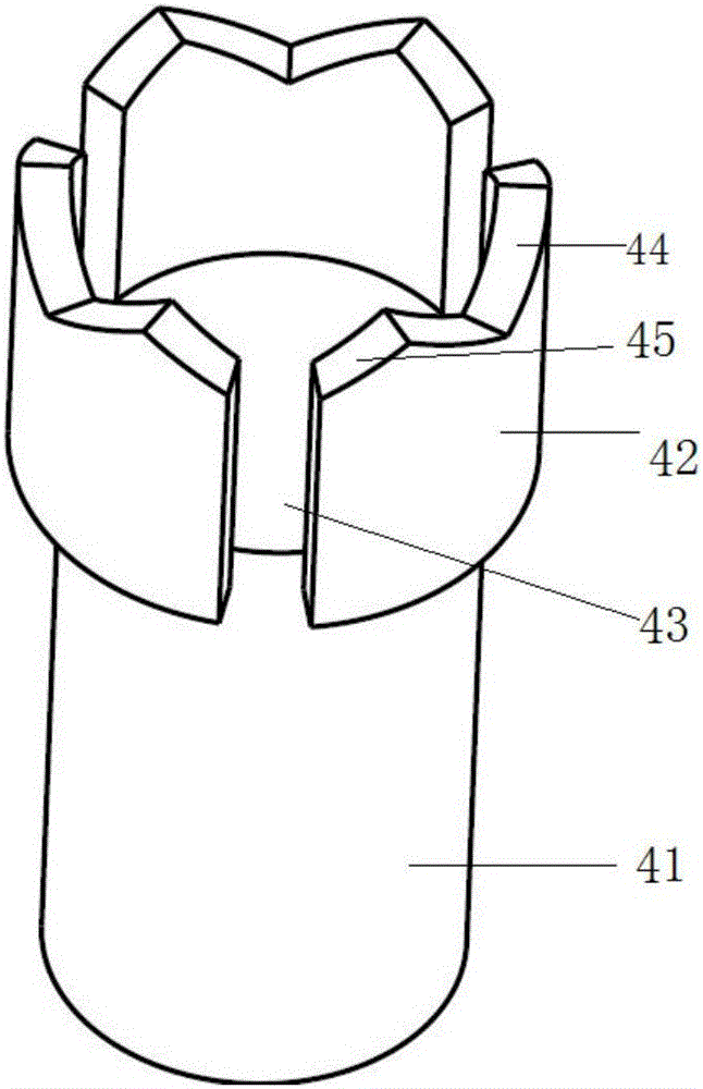
[0026] An embodiment of the present invention provides an electromagnetic unlocking device, the structural schematic diagram of which is as follows figure 1 As shown, it consists of a housing 1, a front cover 2, a coil winding part 3, an armature 4, a rotor 5 and a spring 6. The armature 4 and the rotor 5 are connected in series and placed inside the coil winding part 3, and a pin shaft 57 is provided at the lower end of the rotor 5, and the contact part between the pin shaft 57 and the rotor 5 forms a boss, and the boss and the front cover 2 A spring 6 is arranged between them, and the pin shaft 57 extends out of the front cover 2 through the spring 6 ...


PUM


Abstract

The invention relates to an electromagnetic unlocking device. The electromagnetic unlocking device comprises a circular ring columnar coil winding component (3). The inner ring wall of the coil winding component (3) is axially provided with at least one guide block (31). An inner ring of the coil winding component (3) is provided with an armature (4) and a rotor (5), wherein the armature (4) can axially move along the coil winding component (3), and the rotor (5) makes contact with the lower portion of the armature (4) and can both axially move and circumferentially rotate along the coil winding component (3). The lower end of the rotor (5) is provided with a pin shaft (57) for achieving locking or unlocking with the outside world. A spring (6) is placed between the rotor (5) and a shell. The upper end of the outer wall of the rotor (5) is provided with at least one deep groove and at least one shallow groove. According to the electromagnetic unlocking device, the unlocking or locking state can be kept under the power outage condition.

Description

technical field [0001] The invention relates to the technical field of mechanical connectors, in particular to an electromagnetic unlocking device. Background technique [0002] At present, the commonly used electromagnetic unlocking device is mainly composed of coil winding parts, armature, back cover, spring, pin and shell. , the spring is placed between the rear end of the armature and the back cover, and the back cover is fixedly connected with the shell. When the coil winding is energized, an electromagnetic force is generated to retract the armature and pin against the spring pressure, and the electromagnetic unlocking device is in an unlocked state; when the coil winding is powered off, the spring pressure makes the armature and pin stretch out, and the electromagnetic unlocking device is in a locked state . In order to keep the electromagnetic unlocking device in the unlocked state, the coil winding must always be kept energized, so that the coil winding kept in th...

Claims


Application Information

Patent Timeline
Patent Type & Authority Applications(China)
IPC IPC(8): E05B47/06
CPCE05B47/0607
Inventor 尹骏马俊仲启亮杨中巍黄伯超
Owner BEIJING MECHANICAL EQUIP INST
Why Eureka
Try Eureka