
Shaft structure

A technology of rotating shaft structure and anti-rotating structure, which is applied in the direction of pivot connection, etc., can solve the problems of loose bolts, high processing cost, complex structure of rotating shaft or pivot, etc., and achieve the effect of reducing combination cost and quickly linking two objects

Active Publication Date: 2019-04-02
FIVETECH TECH INC
View PDF8 Cites 0 Cited by
  • Summary
  • Abstract
  • Description
  • Claims
  • Application Information

AI Technical Summary

Problems solved by technology

Among them, the structure and technology of the combination of bolts connecting two objects requires machining screw holes on one object and light holes on the other object, and then use a screwdriver to pass the bolts through the light holes of the first object and lock them into the second object screw holes, so its processing cost is relatively high, and its combination technology cannot meet the requirements of some application fields that do not want the bolts to be turned away, especially if the first object and the second object are in the category of relative rotation, its The process of repeated turning will directly lead to the loosening of the bolts
As for the structure and technology of the existing rotating shaft or pivot combined to connect two objects, although it is not necessary to process a screw hole on at least one object, in order to prevent the rotating shaft or pivot from falling off in the axial direction, usually a screw hole will be formed on the rotating shaft or pivot. One or both ends of the fixed assembly with axial stop effect, the more common fixed components are C-shaped buckle, screw, nut or spring pin, etc., so the structure of the shaft or pivot is more complicated, and the assembly procedure is more complicated. for trouble

Method used


Image

  • Shaft structure
  • Shaft structure
  • Shaft structure

Examples


Embodiment Construction

[0072] In order to fully understand the purpose, features and effects of the present invention, the following specific embodiments are now used in conjunction with the accompanying drawings to further describe the present invention in detail, as follows:

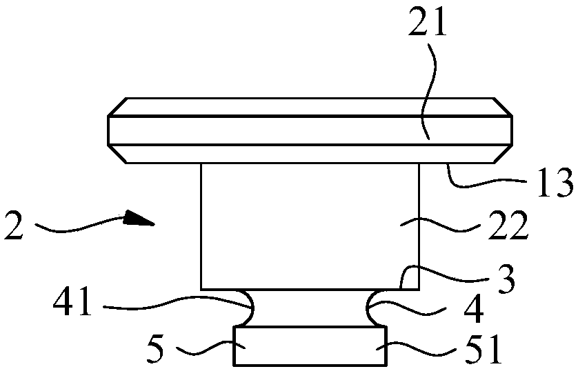
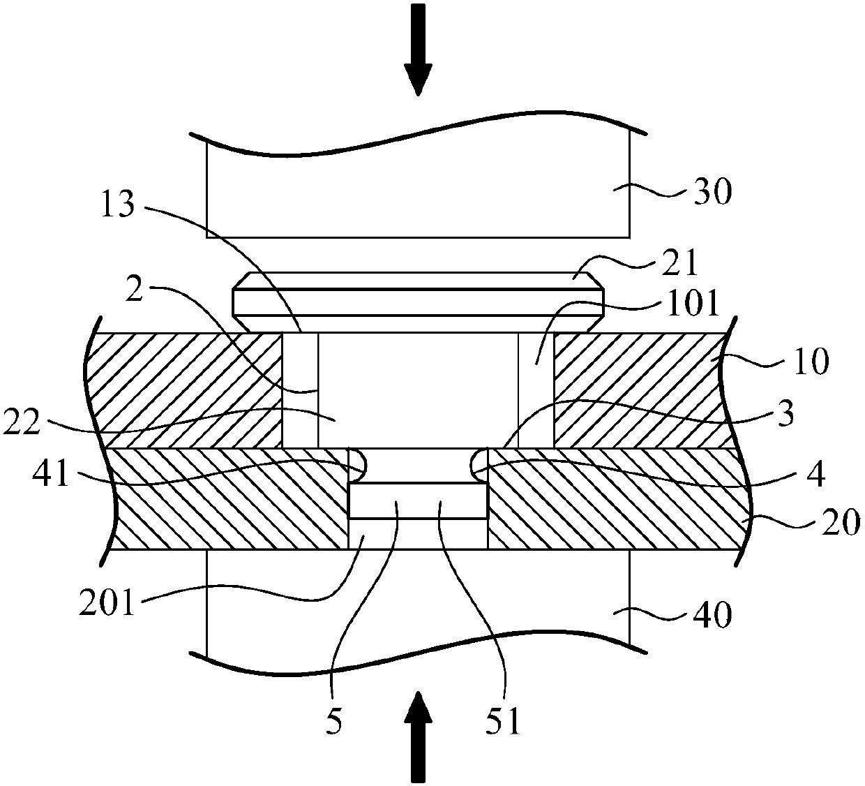
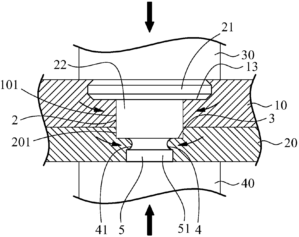
[0073] See figure 1 As shown, it is shown as a shaft structure of the present invention, which is used to quickly link the first object 10 and the second object 20 (such as figure 2 and image 3 Shown), and enable the first object 10 and the second object 20 to rotate relative to each other (such as Figure 4 Shown). Another example figure 1 As shown, the first preferred embodiment of the rotating shaft structure is composed of a shaft body, which includes a T-shaped pressing portion 2 for squeezing or limiting and stopping the first object 10; The second pressing portion 3 of the object 20, the second pressing portion 3 is located at the bottom of the T-shaped pressing portion 2; adjacent to the second pressing portion 3 and u...


PUM


Abstract

The invention provides a rotary shaft structure which includes a T-shaped pressing part or an inverted cone-shaped pressing part which is intended for pressing or limiting a first object; a second pressing part which is intended for pressing a second object and is disposed at a bottom part of the T-shaped pressing part or the inverted cone-shaped pressing part; a material feeding groove which is adjacent to the second pressing part so as to press or limit the materials of the second object; and a stopper which is adjacent to the material feeding groove so as to stop the second object. Therefore, according to the invention, the rotary shaft structure can use a stamping combination structure and method to enable the rotary shaft structure to be in rapid linkage to the first object and the second object and enable the first object and the second object to conduct mutual rotation.

Description

Technical field [0001] The invention relates to a rotating shaft, in particular to a rotating shaft structure that can quickly link a first object and a second object by applying a stamping method, and enable the first object and the second object to rotate relatively. Background technique [0002] The existing combined technology for pivotally connecting two objects and enabling the two objects to rotate relative to each other is mainly connected by bolts, shafts or pivots. Among them, the structure and technology of bolt combination to connect two objects requires processing a screw hole on one object, and processing a light hole on the other object, and then use a screwdriver to pass the bolt through the light hole of the first object and lock it into the second object Therefore, its processing cost is relatively high, and its combination technology cannot meet the requirements of some applications that do not want the bolt to be turned away, especially if the first object and...

Claims


Application Information

Patent Timeline
Patent Type & Authority Patents(China)
IPC IPC(8): F16C11/04
CPCF16C11/04
Inventor 王鼎瑞
Owner FIVETECH TECH INC
Learn More