Magnetic bearing controlling method and device

A magnetic levitation bearing and control method technology, applied in the field of magnetic levitation, can solve problems such as poor stability, achieve the effects of solving poor stability, enhancing stability, and reducing power consumption

Active Publication Date: 2016-11-09
GREE ELECTRIC APPLIANCES INC
View PDF6 Cites 15 Cited by
  • Summary
  • Abstract
  • Description
  • Claims
  • Application Information

AI Technical Summary

Problems solved by technology

[0005] Embodiments of the present invention provide a method and device for controlling magnetic suspension bearings, so as to at least solve the technical problem of poor stability of magnetic suspension bearing systems in the prior art

Method used


Image

  • Magnetic bearing controlling method and device
  • Magnetic bearing controlling method and device
  • Magnetic bearing controlling method and device

Examples


Embodiment Construction

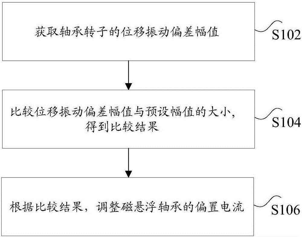
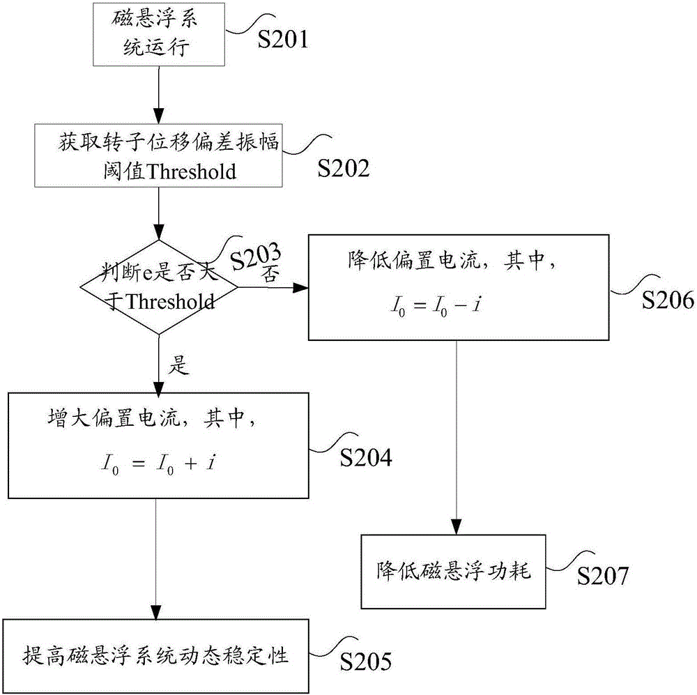
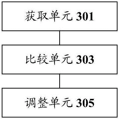
[0021] In order to make those skilled in the art better understand the solutions of the present invention, the technical solutions in the embodiments of the present invention will be clearly and completely described below with reference to the accompanying drawings in the embodiments of the present invention. Obviously, the described embodiments are only Embodiments are part of the present invention, but not all embodiments. Based on the embodiments of the present invention, all other embodiments obtained by persons of ordinary skill in the art without creative efforts shall fall within the protection scope of the present invention.

[0022] It should be noted that the terms "first", "second" and the like in the description and claims of the present invention and the above drawings are used to distinguish similar objects, and are not necessarily used to describe a specific sequence or sequence. It is to be understood that the data so used may be interchanged under appropriate ...


PUM


Abstract

The invention discloses a magnetic bearing controlling method and device. The method comprises the steps of obtaining a displacement vibration deviation amplitude value of a bearing rotor; comparing the displacement vibration deviation amplitude value with a preset amplitude value, so that a comparison result is obtained; and according to the comparison result, adjusting a bias current of a magnetic bearing. By means of the magnetic bearing controlling method and device, the technical problem that in the prior art, a magnetic bearing system is poor in stability is solved.

Description

technical field [0001] The invention relates to the field of magnetic suspension, in particular to a control method and device for a magnetic suspension bearing. Background technique [0002] Magnetic bearings in the prior art generally adopt a differential excitation method. Specifically, differential excitation means that there are two electromagnets with opposite force directions working in the bearing magnet. When the rotor deviates from the reference position, the sensor detects the displacement of the rotor from the reference position at this time, and the position controller converts the displacement The signal is converted into a control current, and through the action of the power amplifier, the current of one electromagnet is the sum of the bias current and the control current, and the other electromagnet is the difference between the bias current and the control current, thereby changing the two electromagnets respectively. The magnitude of the generated suction ...

Claims


Application Information

Patent Timeline
Patent Type & Authority Applications(China)
IPC IPC(8): F16C32/04
CPCF16C32/0451
Inventor 郭伟林李雪胡叨福
Owner GREE ELECTRIC APPLIANCES INC
Why Eureka
Try Eureka