Distributed optical fiber inclination detection device and inclination detection method

A technology of distributed optical fiber and inclinometer device, which is applied in the direction of measurement device, inclination measurement, mapping and navigation, etc., can solve the problems of difficulty in timely measurement, time-consuming and labor-intensive, and high price, and achieves accurate inclination measurement and positioning, and environmental adaptability. Strong, easy-to-use effect

Active Publication Date: 2016-11-09
HOHAI UNIV
View PDF5 Cites 4 Cited by
  • Summary
  • Abstract
  • Description
  • Claims
  • Application Information

AI Technical Summary

Problems solved by technology

At present, fixed inclinometers are expensive and have poor durability. Due to the general monitoring environment is humid or even underwater, and the conditions are harsh, electric inclinometers are prone to failure or damage, especially for slopes with a height of tens or even hundreds of meters. The cost performance of the inclinometer is poor, and the active inclinometer needs manual measurement, which is time-consuming and laborious, especially in extreme weather or corrosive environment, it is difficult to measure in time

Method used


Image

  • Distributed optical fiber inclination detection device and inclination detection method
  • Distributed optical fiber inclination detection device and inclination detection method
  • Distributed optical fiber inclination detection device and inclination detection method

Examples


Embodiment Construction

[0020] Embodiments of the present invention are described in detail below, examples of which are shown in the drawings, wherein the same or similar reference numerals denote the same or similar elements or elements having the same or similar functions throughout. The embodiments described below by referring to the figures are exemplary only for explaining the present invention and should not be construed as limiting the present invention.

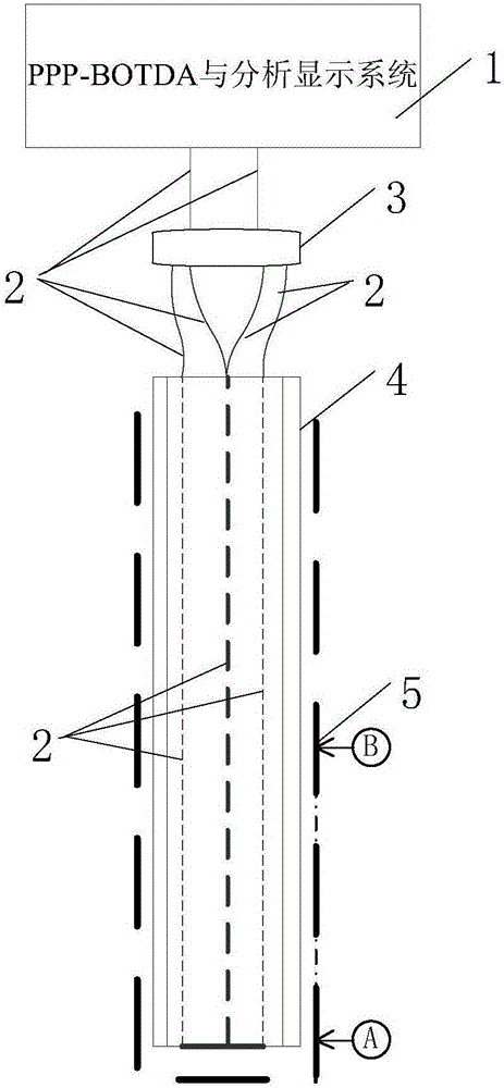
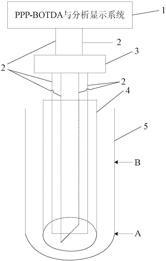
[0021] The distributed optical fiber inclinometer method of the present invention is realized by a distributed optical fiber inclinometer, and mainly includes three parts: pulse-prepump-brilliouin optical time domain analyzer (pulse-prepump-brilliouin optical time domain analyzer, PPP-BOTDA) , fiber optic coupler, fiber optic distributed sensing unit. Through the optical splitting effect of the fiber coupler, one optical transmission route is divided into two optical transmission routes, that is, two U-shaped optical fibers.

[0022] PPP-B...


PUM


Abstract

The invention discloses a distributed optical fiber inclination detection device and an inclination detection method. The distributed optical fiber inclination detection device comprises an optical fiber distributed sensing unit, an optical fiber coupler, a PPP-BOTDA and an analysis display system, wherein the optical fiber distributed sensing unit is connected with the PPP-BOTDA through the optical fiber coupler; the PPP-BOTDA is connected with the analysis display system; the optical fiber distributed sensing unit comprises a sensor bar of which the interior is cross-shaped and hollow, and two U-shaped optical fibers; the U-shaped optical fibers are fixedly embedded or bonded in the sensor bar in a cross-shaped manner; the transverse parts of the U-shaped optical fibers are perpendicular to each other; two ends of each U-shaped optical fiber are connected with the PPP-BOTDA through the optical fiber coupler. The inclination detection method comprises the step of injecting short pulse light and continuous probe light into two ends of each U-shaped optical fiber to measure frequency change of stimulated Brillouin scattering light in the optical fiber and obtain the strain information of each vertical point of the U-shaped optical fiber. The distributed optical fiber inclination detection device and the inclination detection method have the advantages that the operation is simple and convenient, the adaptability to the environment is strong, the maintenance is easy, the cost of the sensing unit is low, and measurement and positioning of inclination are accurate.

Description

technical field [0001] The invention relates to a distributed optical fiber inclinometer and an inclinometer, in particular to a distributed optical fiber inclinometer and an inclinometer using a distributed optical fiber and an internal cross hollow sensing rod embedded or glued to form a sensing unit , belongs to the field of optical fiber inclinometer technology. Background technique [0002] The inclinometer is widely used to observe the horizontal direction change in the soil such as mountain slopes, earth-rock dams, seaside embankments, and building foundation pits. Inclinometers are divided into fixed inclinometers and movable inclinometers, and fixed inclinometers are divided into vertical fixed inclinometers and horizontal fixed inclinometers. The vertical fixed inclinometer can be used to monitor the deformation of the partition wall supporting the deep foundation pit, the ground displacement caused by the tunnel building, the deformation of the embankment and the...

Claims


Application Information

Patent Timeline
Patent Type & Authority Applications(China)
IPC IPC(8): G01C9/00
CPCG01C9/00
Inventor 郑东健陶亮郑诗钰陈波苏怀智谢荣晖沈晶鑫刘永涛刘俊汝
Owner HOHAI UNIV
Why Eureka
Try Eureka